A multivibrator is a self-excited oscillator that produces a rectangular wave, also called a rectangular wave generator. After the power is turned on, a rectangular pulse can be automatically generated without an external pulse!
Multivibrator: Using deep positive feedback, the two electronic devices are alternately turned on and off by RC coupling, thereby generating a square wave output oscillator. Often used as a square wave generator.
Multivibrator constituting a) constituting the amplifierIn pulse technology, a pulse source is often needed to meet the needs of digital operations, information transfer, and system testing. Multivibrators are one of the more common types of pulse sources. Its output waveform is similar to a square wave, so it is also called a square wave generator. Since the square wave is composed of many sine waves of different frequencies, it has been called "multi-harmonic".
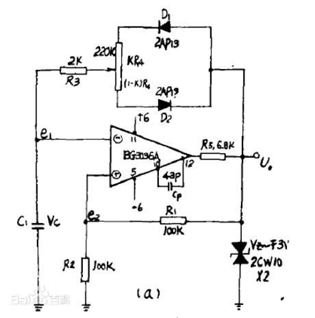
In general, nonlinear wave generators such as triangular waves, oblique waves, sawtooth waves, and square waves are composed of three parts: an integrator (also called a timing circuit), a comparator, and a logic circuit. As shown in the block diagram of the figure. The role of these three parts can be done by only one or two integrated operational amplifiers.

The characteristics of this circuit are:
1, suitable for in the audio range, for a certain fixed
Frequency application,
2, change R: you can adjust the frequency,
3, the stability of the frequency depends mainly on the stability of the capacitor C and Zener diode, so even with cheap components can get a multi-vibrator with a relatively small frequency drift, 2
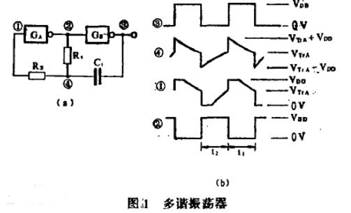
b) Integrated gate circuit compositionThe easiest way to design a multivibrator with a gate is to connect an odd number of gates end to end. However, the accuracy of this oscillator is low, and the oscillation rate cannot be designed as desired. It is only related to the delay time of an odd number of gates. The multi-vibrator with RC timing is simple in structure, high in timing accuracy, and the oscillating frequency can be freely designed.

Figure 1(a) shows the multi-turn oscillator circuit diagram of the RC timing. GA and GB are CMOS inverters, R1 and C1 are timing elements, and Rs is a series resistor. Fig. 1(b) is a waveform diagram of each point, and the operation process can be explained by the circuit shown in Fig. 2. When the power is turned on, the potential at 8 o'clock rises and the potential at 4 o'clock rises. When the 4-point potential rises to the Vtv level of the GA gate, GA is turned on, 2 points jump to low level, and 3 points rise to VDD level. Then C1 passes through the "P" tube of GA, and the "n" tube of R1, C1, and GA discharges. During the discharge process, the potential at 4 points decreases according to the time constant of R1 and C1, and when the potential at 4 points falls to the VRA level, G The gate is closed, 2 points jump to the level close to VDD, 8 points jump to near 0V, 4 points potential jump to (VRA - VDD) level. C1 is then charged through the "p" tube of G, the "n" tube of C1, R1, GA. Just oscillate like this. A complementary output waveform is obtained at 3 and 2 o'clock.
c) the composition of body tube frequency stabilizationTransistor multivibrators (hereinafter referred to as bistable) are mostly used in digital devices such as electronic computers and electronic switches, or in measuring instruments such as counters and digital voltmeters.
As a bistable circuit, the Eocles-oJrdan type circuit is very different from the current switching type circuit. Due to its simple circuit structure and low power consumption, almost all cases except high-speed operation Adopting an Ericsson-Jordanian circuit.
Four) 555 integrated circuit componentsThe 555 timer is a medium-scale integrated device that combines analog and digital functions. The device is low in cost and reliable in performance. It requires only a few external resistors and capacitors to implement multiple functions. Because the circuit is simple and reliable, it is widely used in many fields such as signal generators, audio alarm circuits, electronic toys, and home appliance control. In the experimental teaching of electronic technology in colleges and universities, the experiment of 555 multi-vibrator is a must-have for the classic.
V) Other methods of compositionThe multivibrator can also be composed of discrete components or integrated Schmitt triggers.
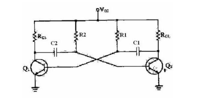
Multi-vibrator circuit structure and working principle The circuit structure is as follows:
1. Change the two resistance coupling branches of the flip-flop circuit to the capacitive coupling branch. Then, the circuit has no steady state and becomes an unstable circuit.
2. Power on: Due to the small difference in circuit parameters, positive feedback makes one tube saturated and the other cut off, and a temporary steady state appears. Let BG1 be saturated and BG2 be cut off.
working principle:1. Positive feedback: At the instant of BG1 saturation, VC1 is abruptly changed from +EC to near zero, forcing BG2's base potential VB2 to drop to near-EC instantaneously, so BG2 is reliably cut off.
2. The first temporary steady state:
C1 discharge
C2 charging
3. Flip: When VB2 rises to +0.5V with C1 discharge, BG2 starts to conduct, and BG1 is turned off by positive feedback, and BG2 is saturated.
4. The second temporary steady state:
C2 discharge
C1 charging
5. Constantly reciprocating, it forms a self-oscillation.
6. Oscillation period: T=T1+T2=0.7(RB2*C1+RB1*C2)=1.4RB*C
7. Oscillation frequency: F=1/T=0.7/RB*C
8. Waveform improvement: It can be used with a monostable circuit and a correction diode circuit.
The role of the multivibratorA multivibrator is used to output a square wave, especially a square wave with a certain duty cycle. According to the relevant theory of signals and systems. The square wave is a superposition of many more harmonics. The role of a multivibrator is to create a multi-harmonic signal that is composed of related components.
Multivibrator application
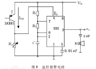
The above figure is a simple temperature-controlled alarm circuit composed of a multi-vibrator. In the figure, the ICEO is the reverse saturation current flowing from the collector region to the emitter region when the triode T is open, called the penetration current. ICEO is one of the thermal stability parameters of the triode. At room temperature, the ICEO of the silicon tube is smaller than the ICEO of the neon tube; when the temperature rises, the ICEO increases, and the ICEO of the neon tube increases rapidly with increasing temperature. When choosing a transistor, it is generally desirable to have ICEO as small as possible. However, this circuit uses a neon tube that has a large penetration current and is sensitive to temperature changes, and uses its ICEO to control the voltage of the 4-pin of the 555 timer reset terminal. In the figure, the 555 timer and R1, R2 and C form a multivibrator, and its reset terminal 4 pin RD is grounded through R3. At room temperature, the penetrating current ICEO is small, generally 10 to 50 μΑ, and the voltage generated at 3 is lower. If the voltage at 555 reset terminal 4 pin RD is lower, then 555 is in reset state, and the multivibrator stops. Vibration. When the temperature rises or there is a fire alarm, the ICEO increases, and the voltage generated on R3 rises, causing the 555 reset terminal 4 pin RD to be at a high level, the multivibrator starts to oscillate, and the speaker emits an alarm sound.
The ICEO values ​​of different transistors in the temperature control alarm circuit have a large difference, so it is necessary to change the resistance of R3 to adjust the temperature control point. The method is to first place the temperature measuring component T at the temperature required to alarm, and adjust R3 so that the circuit just sounds an alarm. The pitch of the alarm depends on the oscillation frequency of the multivibrator, determined by components R1, R2, and C. Changing these component values ​​can change the pitch, but requires R1 to be greater than 1kΩ.
Shenzhen Sunwind Energy Tech Co.,Ltd , https://www.sunwindbatterylm.com