AC motor speed control is superior to traditional DC motor speed control, and it is also superior to speed regulation methods such as variable speed control, variable speed control, and cascade speed control. Its characteristics are: smooth speed regulation, wide speed range, high efficiency, good performance, simple structure, hard mechanical properties, complete protection functions, stable, safe and reliable operation, and optimal speed parameters in the production process. It is an ideal speed regulation. the way.
I. Overview
In the sugar industry in China, many important production equipments are high-energy-consuming equipment. The power-drawing of equipment is inseparable from the speed regulation. Due to the limitations of the technical conditions at design time, many equipments are often driven at the time of design. Adopting energy consumption regulation, AC motor variable frequency speed regulation is a new technology developed on the basis of modern microelectronics technology. It is not only superior to traditional DC motor speed regulation, but also than the speed regulation, pole changing speed regulation, cascade Speed ​​control and other speed control methods are superior. Its characteristics are: smooth speed regulation, wide speed range, high efficiency, good performance, simple structure, hard mechanical properties, complete protection functions, stable, safe and reliable operation, and optimal speed parameters in the production process. It is an ideal speed regulation. the way.
Application practice proves that the frequency conversion speed regulation of AC motors can generally save about 30%. At present, the industrialized developed countries have widely adopted variable frequency speed control technology. In China, it is also a new energy-saving technology that the country mainly promotes. Inverters are used in fans, pumps, presses, and centrifuges in the sugar industry to achieve significant energy savings.
two. working principle
1, the original water supply system conditions
The original water supply system consists of a two-way pipe network system. The first line of pipe network water supply pumps is six, and the water pump motors are: 110KW five and one 75KW; the second road pipe network pumps are six, and the water pump motors are: 155KW five. Taiwan, 220KW. The pump switching depends on the duty personnel to switch according to the pressure, the water pressure is used for the change of the production water consumption and the switching change of the pump group is relatively large. The switching of the pump group has a great impact on the power grid, and the water pressure and Flow requirements require a backflow valve to adjust.
2, frequency conversion energy-saving reform program
From the above system operating conditions, we can see that the system is suitable for frequency conversion and energy saving transformation. The transformation scheme is as follows:
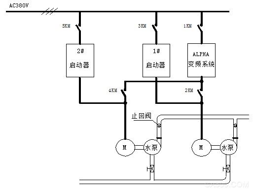
The system adopts variable frequency control and presses the pressure sensor on each pipe network to detect the water pressure of the pipe network immediately. According to the change of the production water volume, the frequency conversion control system automatically adjusts the speed of the water pump motor to control the water supply of the system and ensure the water pressure of the pipe network. Constant. The first pipeline network consists of 110KW frequency conversion energy-saving system to control two pump motors, one for use and one for standby, and the other four for power frequency control; the second pipeline network is controlled by a 220KW energy-saving frequency conversion system and a 220KW pump motor and a 155KW pump motor. One is used and one is prepared, and the other four are controlled by power frequency. After the transformation, the energy-saving effect is dramatic, and constant pressure water supply has greatly improved the production process. The transformation system control chart is as follows:

a Pump characteristics and parameters:
The power purely used for pumping is called effective power. Effective power = (1000QH)/(75×60/0.736) = QH/6.11 (kW)
In the formula, Q is the flow rate (m3/min); H is the total head (m).
The weight of 1m3 of water in the lift is 1000kg, therefore: Pump shaft power = (effective power) / pump efficiency (kW)
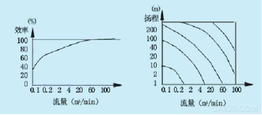
Motor output power = (1.05 ~ 1.2) × shaft power (kW)Due to the size of the pump head and the type of the pump, the efficiency of the pump can not be determined, and the general efficiency curve of the standard pump
as shown in picture 2.
In view of the error in the design and manufacturing of the pump, the output power of the motor should be 5 to 20% of the calculated value of the shaft power, and then the power of the motor should be obtained based on the flow rate and the head. Figure 3 shows the flow rate and lift characteristics. .

Fig. 2 Efficiency of general standard pump Fig. 3 Flow and head characteristic curve
b The water resistance characteristics of the pipe network When the water resistance R of the pipe network remains unchanged, the relationship between the water volume and the over-water resistance is uncertain.
That is, the amount of water Q and the over-water resistance h change according to the law of resistance, and its expression is:

In the formula, H - over water resistance R - water resistance coefficient.
The curve of H=f(Q) is a water resistance characteristic curve in the form of a parabola, as shown in FIG. 4 . As can be seen from FIG. 4 , the larger the water resistance coefficient R is, the steeper the curve is, ie, the greater the overwater resistance.
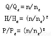
c Energy saving principle of pump type speed control According to the fluid mechanics, the quantity of water Q is proportional to the first speed of the speed, the pressure H is proportional to the square of the speed, and the power P is proportional to the cube of the speed.

Where: Qe - rated wind of fan, pump
(flow;He—rated pressure of fans and pumps Pe—the rated power of fans and pumps;
ne—The rated speed of fans and pumps.
According to the above formula, if the efficiency of the pump is certain, when the required amount of water is decreased, the rotation speed can be proportionally decreased. At this time, the shaft power of the water pump is decreased by the established relationship.
In addition, according to the relationship curve between the characteristic curve of the pump and the water resistance characteristic, the energy-saving effect of the fan and the pump can also be clearly seen. Fig. 5 is a schematic diagram of the speed and energy saving principle of the fan and the water pump. The curve H in the figure is the Hf (Q) curve at a constant speed, and the water resistance and wind resistance characteristic curve R1 intersects with point A. The corresponding air volume is Q1.
At this time, the axial area enclosed by the shaft power Q1AH1Q of the fan and the pump is proportional to the area. When the damper or valve is used to reduce the air flow from Q1 to Q2, the new wind resistance and water resistance characteristic curve H intersect at point B. At this time, the power of the fan shaft is proportional to the square area enclosed by Q2BH2Q. If the speed control method is used to reduce the rotation speed of the fan and the pump to n2, the corresponding fan characteristic curve H and the resistance characteristic curve R2 intersect at the point C. At this time, the square area enclosed by Q2CH3Q, which is proportional to the power of the fan shaft, is significantly reduced, indicating that the shaft power is greatly reduced and the energy saving effect is significant.

Fig. 4 Water resistance characteristic diagram Fig. 5 Water pump speed regulation and energy-saving diagram
Third, the system configuration
1, constant pressure water supply function
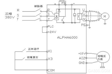
6000 frequency conversion system built-in PID regulator, pipe network remote pressure gauge immediately detects the pipe network pressure and converted into 0~10V voltage signal, directly into the analog voltage input of the inverter, set the given pressure value, PID parameter value, inverter Built-in PID operation controls the output frequency. System parameters can be adjusted during actual operation, making the system control response fast. Pipe network pressure can be arbitrarily given according to the production process. The frequency conversion system automatically follows the control and keeps the pressure set by the pipe network constant. This not only saves water pressure requirements for the production of sugar. The wiring diagram is as follows:

2, the pump group switching instructions
The system can instantly detect the water pressure of the water supply network. When the existing pump group cannot meet the needs of the production water or exceed the need of the production water, the system can automatically issue the input or remove the instruction of the pump group and give the sound and light switching pump group alarm to indicate the duty. The personnel switched the pump group to ensure the need for production water.
3, work frequency switching function
The sugar industry water supply system has high reliability requirements. Once the failure will have a serious impact on the entire production, the system is equipped with a work frequency switching function. Under normal circumstances, the system operates in constant pressure and constant pressure water supply. When the inverter is in the event of a fault or routine maintenance, it can immediately switch to the power frequency operation and start the pump with the original backup auto-buck starter system to ensure water supply. Continuity, the reliability of the entire system can well meet the production requirements. The two sets of starting systems are electrically interlocked to prevent misoperation and ensure the safe operation of the system.
Fourth, the income after the transformation
1. Extend the service life of equipment and pipe network and reduce system maintenance workload.
Due to the use of variable frequency and constant voltage control, the start of the water pump is a soft start, eliminating the impact of the impact torque on the motor when the large motor starts, the impact of the water pump at startup is greatly reduced, and at the same time, the soft start and the water pressure are constant pressure control, eliminating The water hammer effect on the pipe network at startup is no longer occurring. Therefore, the service life of the original equipment is prolonged, the failure rate is greatly reduced, and the workload of system maintenance is reduced.
2. Improve the quality of water supply and improve the reliability of the entire system.
After adopting the frequency conversion constant pressure control system, the water supply pressure can be adjusted very smoothly, and the on-duty personnel can control the system more stably and freely. As the production process changes, the system's water supply pressure can be easily adjusted. Due to the adoption of the new system, the failure rate is greatly reduced, and the two startup systems can be used as backups to each other, ensuring the continuity of the system water supply and providing a reliable guarantee for the optimal operation of the system economy.
3, to improve the power condition of the factory.
The use of variable-frequency soft-start eliminates the impact on the grid when the original start-up system starts up. The new system has a power factor of up to 0.95 and an efficiency of up to 0.98. The operating current of the system is greatly reduced, and the line loss is also greatly reduced, improving the plant. Electricity situation.
4. Significant energy saving effect and considerable economic benefits.
When the original system is running to maintain the water pressure is basically constant, in addition to the repeated need to repeatedly cut the pump group, but also need to use the return valve for small-scale adjustment, pump repel the impact of the power grid on the need to consume energy, return valve adjustment basic Does not reduce the power consumption of the pump. After adopting frequency conversion, the variable frequency pump set can automatically adjust the speed of the pump motor according to the water pressure required for production, keep the pressure of the pipe network constant, the instantaneous range of the variable frequency pump set to be adjusted is wide, the number of switching of the pump set is greatly reduced, and the energy saving effect of the system is significant. On average, the energy saving rate of the entire system is about 30%, and the economic benefits are considerable.
5. Reducing the work intensity of on-duty personnel
After the original system has been modified, the water pressure in the pipe network is automatically detected and controlled, and the return valve does not need to be adjusted. The pump group has an audible and visual alarm indication. The on-duty personnel do not worry that the pump group is not switched on and the return valve is opened in time. The water pressure is too low or too high to affect production accidents.
Description of zipper braided sleeve
Whether your problem is getting past large connectors or not wanting to disconnect complex cable runs, this Zipper Cable Sleeve side-entry braided wrap is an ideal cable management solution. Zip up cable sleeving is great for wire installations in which only a small portion of the bundle needs to be concealed, and is easily removed and relocated at your convenience.
Our expandable braided zipper sleeving offers exceptional cable protection, but is really used to tidy up exposed cable runs. TV, computer and phone setups can all have a clean and organized cables instead of those ugly cable nests.
Automotive and marine applications such as aftermarket speaker systems, GPS or other component accessories that may need cable organization can benefit from this braided sleeving.
A great feature to this side entry zipper cable wrap is the ability to expand, this is due to the loose braided weave which allows the flexibility if your cords create a tight fit.
The purpose of putting a protective cover on the wire harness is to reflect the quality and stability of a wire harness protection braided sleeve, and it is inseparable from the outer protective layer, such as the wire harness protection braided sleeve used outside the wire harness, which is good or bad. Some aspects determine the quality of a set of harnesses. During these years, when visiting customers, I often see or hear the customer's reaction. Some mechanical protection of the wire harness used to protect the wire harness protects the quality of the braided sleeve. For example, some machines will generate heat when working, which requires the material of the wire harness protection braided sleeve to have better temperature resistance, but often see It is a lot of wire harnesses that have been used for a year or even months to protect the braided sleeve from breaking, aging, falling off, and more serious melting or fire.
Zipper Cable Sleeve ,Zipper Sleeving For Cable,Zipper Braided Sleeving,Wire Management Sleeve
Shenzhen Huiyunhai Tech.Co.,Ltd , https://www.hyhbraidedsleeve.com