0 Preface
With the development of embedded technology and communication technology, in the field of mobile phones, smart phones have become the mainstream trend of mobile phone development. Currently in the field of smart phones, processor selection, operating system selection and application development are hot topics. In the course of computer related majors in colleges and universities, more and more related content of smart phones is involved, and more and more students are also engaged in the learning and development camp of smart phones. Therefore, it is necessary to provide relevant experimental equipment for these students. This paper proposes to build a smart phone hardware experimental platform based on Samsung S3C2410 chip, and combines wireless communication module to realize smart phone short message function. It provides a platform for students to carry out experiments related to smartphones. Through this platform, students can complete various software developments during smartphone design, and change the traditional verification-based experimental platform model, which is conducive to the cultivation of students' innovative ability.
1 Smartphone hardware and software experimental platform design There are three main hardware implementation methods for mobile phones:
(1) Only baseband chips, usually called function phones;
(2) Baseband chip plus coprocessor, this kind of product enhances the multimedia processing function based on the function phone;
(3) Baseband processor plus application processor. This is the design used in smartphones, with baseband processors for communication and application processors for multimedia and other applications.
When designing a smartphone hardware platform, you need to pay attention to the following aspects:
(1) The application processor should have a high enough frequency to ensure the running speed of the system, so that various applications can run smoothly;
(2) The system should have enough memory space to store application and user data;
(3) It has a good human-computer interaction interface, and users can operate it conveniently. The baseband processor has stable performance and ensures real-time communication.
1.1 Hardware platform design hardware mainly includes debugging interface, storage system, GSM/GPRS communication module, and human-computer interaction module. The core controller chip uses Samsung's S3C2410 processor and the frequency is stable at 203 MHz. As an experimental platform, the basic functions of the smartphone are completed, and a large amount of data processing is not required, so the 203 MHz main frequency can guarantee the running speed of the system. The system uses 64 MB SDRAM and 64 MB NANDFLASH as the storage system to ensure system and user storage space. In communication, the application processor connects to the baseband processor via UART2, ie GSM/GPRS communication module, and the GSM/GPRS module uses SIMCOM module of SIMCOM. The module has a complete GSM/GPRS tri-band/quad-frequency solution, supporting GSM calls and short Messaging and GPRS data transmission can be easily controlled by AT commands. The system displays the graphical operation interface through the LCD, and adopts the touch screen instead of the traditional keyboard operation, the interface is more friendly and the operation is more convenient. At the same time, an extended interface is provided for students to extend other functions of the smartphone, such as web browsing using an Ethernet interface. The hardware block diagram of the whole system is shown in Figure 1.
This article refers to the address: http://
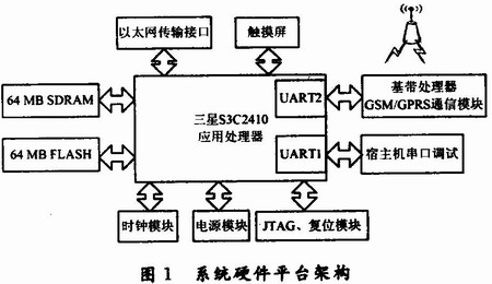
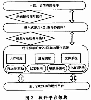
1.2 System Software Platform Design The function of the system software platform is to provide a platform for application development. The system software is designed based on the embedded Linux operating system and the embedded GUI Qtopia. The architecture of the entire software platform is shown in Figure 2.
1.2.1 Bootloader
The Bootloader is the first piece of code that runs after the system is powered on. The main job is to complete the hardware initialization and prepare the conditions for loading the operating system. Its implementation is hardware-dependent, and the bootloader of different architecture development boards varies greatly. In order to better support the target board's hardware devices, the system chose to develop its own Bootloa-der in the ADS1.2 integrated development environment. The implementation process of Bootloader is mainly divided into the following two stages:
(1) Mainly perform initialization processing work closely related to the CPU core and the storage device. This part of the code is usually written in ARM assembly instructions and is included in start. In the S file. Usually includes some steps:
1 hardware initialization work. This includes turning off the watchdog; masking all interrupts; setting the processor clock and operating frequency; initializing external registers; initializing the stack pointer.
2 Prepare the RAM space for phase (2), and copy the code of phase (2) to RAM, and jump to the entry point of phase (2).
(2) Complete the general startup process and provide driver support for the target device. This part will be copied and executed in RAM. This code is usually implemented by C language and has strong readability and portability.
Usually include the following steps:
1 Complete the general I/O setting by the set_gpios() function;
2 through meree_map_init (), mmu_init () function to complete memory mapping and memory management unit initialization;
3 initialize the MTD device, using the mtd_dev_init() function;
4 copies the Kernel image file and the root file system image in NAND FLASH into the RAM space;
5 jump to the first instruction of the kernel.
At this point, the bootloader's task ends, and the next task is completed by the operating system.
1.2.2 Trimming and porting of the operating system The operating system is responsible for managing the entire peripheral device and scheduling various software tasks. This is very important for smartphones. The operating system adopts open source and free Linux, and is based on embedded Linux 2.6. The main migration process includes setting up the development environment, downloading the kernel source code, modifying the configuration file, configuring the kernel, compiling the kernel, and compiling the module. The process is roughly the same, here is a brief introduction:
(1) The cross-compilation tool on the host machine uses arm-linux-gcc-3.4.1;
(2) Modify commom-smdk. c file, set the partition for NANDFLASH;
(3) Modify the configuration file fs/Kconfig to enable the kernel to support devfs when it starts up;
(4) configure the kernel;
(5) Compile the kernel and modules, and use the Busy-box tool to create the yaffs file system.
1.2.3 Embedding the GUI GUI Qtopia's portable embedded GUI is used to develop the graphical interface of SMS and telephony applications. This article uses Trolltech's Qtopia as the graphical interface library, and the version is Qtopia-core-opensou rce-src-4. 4.3. The main tasks of the transplant are:
(1) Modify qmouselinuxtp_qws. h file, enabling Qtopia to support touch screen;
(2) configuration, compilation, and installation;
(3) Copy the relevant library files to the development board and set the environment variables.
2 Application Design Phone and SMS applications are the most basic and core applications of smartphones. The main tasks of the phone text message application design include: the process design of the phone text message application, the serial communication of the communication module and the application processor, and the development of the phone and short message application interface.
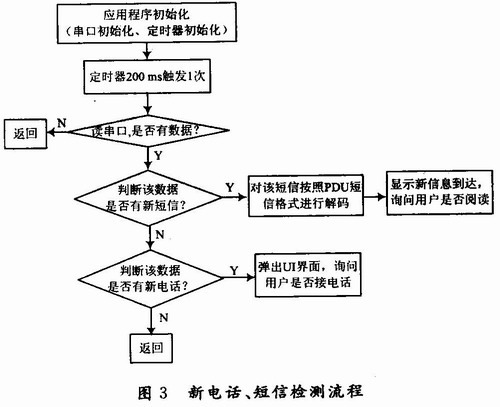
2.1 Phone/SMS Application Process The application uses a timer function to control the flow of the entire program. The timer is triggered once every 200 ms.
The detection process of the new phone and the new message is shown in Figure 3. The application initialization needs to initialize the interface between the GSM/GPRS communication module and the application processor, and also defines a 200 ms triggered timer. After the system is initialized, the timer triggers to start reading the serial port data for judgment. When there is no data on the serial port, wait for the next timer to start; when the serial port has data, judge the data of the serial port; when there is a new short message prompt in the data, decode the short message according to the decoding format of the PDU short message, and call The UI interface prompts the user to arrive at a new short message and asks the user whether to read it; when there is a new phone prompt in the data, the UI interface is called to ask the user whether to answer.
When you need to send a text message or dial, the application flow is shown in Figure 4. When the user invokes the sending interface to edit the short message and enters the receiving party and clicks the send button, the application first determines whether the short message center number and the received information number are correct. If not, the user is prompted to be wrong; if the number and number format are both If it is correct, the content of the short message to be sent is encoded according to the PDU short message format, and an AT command is written to the serial port to send the short message. The process of dialing and hanging up the phone is very simple. You only need to write the ATD+ dialed number and ATH to the serial port. When the dialing error occurs, the user is prompted to dial the error.
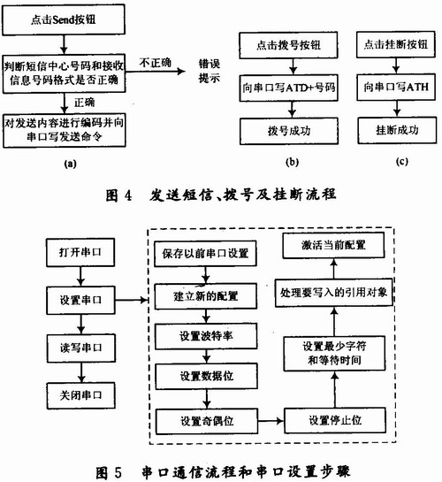
2.2 Communication module serial communication realization Serial port is the interface connecting the smart phone application processor and GSM/GPRS communication module. The serial communication process is to open the serial port, serial port initialization setting, read/write serial port, close the serial port, as shown in Figure 5. Show.
Initialize the serial port during initialization of the application. The initialization of the serial port is mainly to set some parameters of the serial port, including the following parts: save the previous serial port settings, establish a new configuration, set the baud rate, set the data bit. , set parity, activate current configuration, process reference objects to be written, set minimum characters and wait time, set stop bits. Only after the serial port is initialized can the application perform the corresponding operation on the serial port.
2.3 Design User Interface The user interface is the interface for human-computer interaction. This article uses the interface design tool Qt commonly used under Linux to design various UI interfaces required by the application. The interface for making calls and sending text messages designed in this paper is shown in Figure 6.
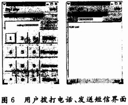
When clicking a button on the interface, such as dialing and sending, using its signal and slot mechanism, it can associate with the corresponding functions of the underlying layer, such as a dialing function and a sending function, to realize the function of dialing and transmitting information. Users can use this interface to make calls and send text messages.
3 Conclusion This paper designed a smart phone phone text message experiment module based on embedded Linux. The smartphone software and hardware platform was built, and the application design of the phone text message was completed. It provides a platform for students to conduct experiments on smartphone development. At present, this platform has been applied to the innovative experimental platform of the Communication Laboratory of Beijing University of Chemical Technology, and provides services for students to conduct smartphone experiments. In the subsequent design, consider embedding the embedded database into the application to implement the functions of the business card holder and the inbox in the phone text message, and develop other applications based on the hardware platform, such as MP3 playback, to provide Students conduct trials and studies.
Our circuit board manufacturing company has been serving high-tech fields such as electronic consumption, communication equipment, automotive electronics, power equipment, industrial control, medical care, security and military industry for a long time.
After establishment of more than 15 years,Liandajin always upholds the principle of "customer-centered and quality-oriented"to provide high-quality products and good services to customer.
6layers PCB Board,4Layers PCB,8layers PCB,Multilayer Curcuit Board,Multilayer Printed Circuit Board
Huizhou Liandajin Electronic Co., Ltd , https://www.ldjcircuitboard.com