introduction
This article refers to the address: http://
Embedded system refers to application-centered, computer-based, software and hardware tailoring, adapting to the application system's strict requirements for function, volume, cost, reliability, power consumption. The embedded system is application-oriented, and the hardware selection and software development mode of the system must be determined according to the specific application.
Permanent magnet brushless DC motor is one of the hotspots in the field of motor control research, which is closely related to its inherent technical advantages: electronic commutation replaces the mechanical commutation of brushed DC motor. Basically, it eliminates a series of problems such as sparks, noise, and high failure rate caused by brush commutation of ordinary brushed DC motors, and at the same time makes the performance of the system comparable to that of ordinary brushed DC motors. Applications. The electronic commutation of a permanent magnet brushless DC motor is inseparable from the rotor position signal of the motor. The traditional method is to detect the position signal by using a Hall device or other position sensor, which makes the maintenance and manufacture of the system inconvenient, and because of the sensor The unstable working characteristics bring some hidden dangers to the safe operation of the system. Therefore, the position sensorless solution has aroused great interest.
This paper combines the development of the sensorless permanent magnet brushless DC motor control system with Microchip's PIC18F452 microcontroller as the main control device, and uses the embedded real-time operating system μC/OS-II as the software development platform to discuss the embedded system in detail. Development model and process.
2. System hardware platform design
The first step of embedded system design is to combine the specific application, comprehensively consider the system's requirements for cost, performance, scalability, development cycle, etc., determine the system's main control device, and use it as the core to build the system hardware platform. .
The key issue of the position sensorless permanent magnet brushless DC motor control system is position detection. A number of position detection schemes have been available, and the back EMF method has been widely adopted due to its simplicity and practicality. The principle of the back EMF method is: based on the three-phase voltage of the motor, the three-phase potential zero-crossing signal is obtained by hardware detection circuit or software algorithm, and then the phase of the commutation is obtained by software phase shift, and the commutation logic is completed at the commutation time. The commutation, triggering the inverter bridge to work with the appropriate conduction sequence, thus ensuring the normal operation of the motor.
The position sensorless control of permanent magnet brushless DC motor with back EMF method puts higher requirements on system hardware:
1 three external interrupt input pins to facilitate the capture of three opposite potential zero-crossing signals;
2 at least one PWM module to achieve chopper speed regulation of the motor;
3 Rich timer resources to complete software phase shifting, speed measurement and other functions;
4 multi-channel AD conversion module, capable of sampling speed and current and voltage signals of the main circuit;
5 hardware multiplier to ensure the speed and current regulator speed;
6 sufficient program and data memory for system expansion;
7 High-speed system operating frequency to ensure strong real-time performance of the system;
8 Rich communication modules to facilitate interconnection of systems with other embedded systems.
For the design of the position sensorless permanent magnet brushless DC motor control system, there are many special chips available, but in order to further improve the system performance and enhance the design flexibility, smart devices such as DSP or dedicated microcontroller are often used. However, this increases system performance while increasing system development costs. In order to design a high-performance, low-cost development platform, the requirements of the system hardware for the application, taking into account the high cost performance of the PIC18F452 microcontroller, select it as the main control device.
The PIC18F452 is an enhanced 8-bit microcontroller from Microchip. It uses a reduced instruction set (RISC) design with a two-stage pipeline and a maximum operating frequency of 10 MIPS to meet the real-time requirements of the system. The instruction bus is 16 bits wide. The data bus is 8 bits wide; the MCU has 32K bytes of FLASH program memory, 1.5K bytes of data memory and 256 bytes of EEPROM for easy system expansion; it has 8×8 hardware multipliers; Provides 18 interrupt sources, two interrupt priority levels, and interrupt priority configurable. The PIC18F452 microcontroller is equipped with a wide range of peripheral modules, which greatly simplifies the design of the peripheral circuits of the microcontroller. At the same time, Microchip provides a powerful instruction set for the PIC18F series of microcontrollers, a total of 77 instructions, most of the instructions are single word (2 bytes) storage, single cycle execution, application code storage compression rate, instruction execution efficiency high.
The hardware block diagram of the system composed of PIC18F452 as the main control device is shown as in Fig. 1.
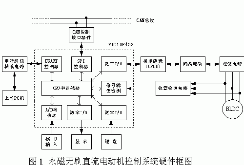
It is worth noting that:
1 The commutation logic in the system is completed by the programmable logic device, mainly to improve the reliability of the system. From the functional point of view, it can be completely realized by the single chip microcomputer;
2 The speed detection of the motor can be calculated by software according to the position signal, so the speed sensor is omitted;
3 The analog input is the speed reference signal of the motor.
3. Embedded system software development model
For a simple application system, the software development mode of the system is usually shown in Figure 2, called the front-back system (also known as the infinite loop system).
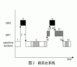
In the front and back system, the application is an infinite loop. The function is called in the loop to complete the corresponding operations. These operations are called background tasks; the interrupt service program handles asynchronous events, which is called foreground behavior. Because the information provided by the interrupt service routine is always processed until the background program runs to process the information, the worst case task response time is equal to the execution time of the entire loop. Because the execution cycle of the background loop is not constant, the application software development based on the front and back background mode, although the design process is simple, the real-time performance of the system is not guaranteed.
In order to improve the real-time performance of the system, a software development mode based on the embedded real-time operating system (RTOS) can be adopted. There are two types of RTOS: non-releasable kernels and deprivatable kernels. Generally, commercial decommissioning kernels are used. Therefore, this paper only discusses such RTOSs. The kernel structure is shown in Figure 3.
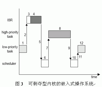
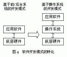
The RTOS subdivides the entire application into multiple tasks, each of which performs a specific function and is given a certain priority, with its own task control block and stack space. Generally, each task is an infinite loop in the program structure, which has multiple states - sleep state, ready state, running state, suspended state, and interrupted state. The system kernel always runs the high-priority task in the ready state first, and the interrupt service program can preempt the CPU. When the interrupt service program is completed, the system kernel runs the task with the highest priority in the ready state (not necessarily the interrupted task). ). It can be seen that the RTOS-based software development mode optimizes the system's task response time. More importantly, this development model transforms the functional-oriented application development into the application development of the surface task, which simplifies the logical structure of the system design. At the same time, because of the RTOS, the visibility of the application software to the underlying hardware is shielded. Converting the two-layer structure of the previous software system into a three-layer structure (as shown in Figure 4) greatly facilitates software expansion and hardware upgrade of the system.
For PIC18F series MCUs, the commonly used embedded real-time operating systems are: μC/OS-II, Salvo, CMX, PIC18OS, etc. They are all deprived real-time kernels, as detailed in Table 1.
Table 1 Several embedded real-time operating systems for PIC18F series microcontrollers
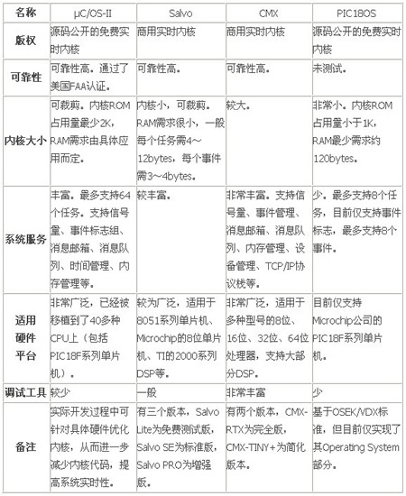
Combined with the specific application of this paper, considering the hardware resources of the system and the characteristics of several real-time operating systems mentioned above, the operating system-based software development mode is selected, and μC/OS-II is selected as the system software platform.
4. Application software development based on μC/OS-II
μC/OS-II is a portable, curable, croppable and deprivable multi-tasking real-time kernel. Application development must first be completed on a specific hardware. μC/OS-II fully considers portability in the process of writing. Most of its code is written in ANSI C. The code related to the processor is concentrated in OS_CPU.H, OS_CPU_A.ASM, OS_CPU_C.C. In the three files, as long as these files are rewritten for specific hardware, the migration can be completed.
After the migration is successful, you can start writing the application. RTOS transforms function-oriented application development into application development for face-to-face tasks. Therefore, the process of software development is to subdivide the application system into multiple tasks according to functions, then implement each task and determine the appropriate priority for the task; For highly demanding operations, you need to write related interrupt service routines.
The basic conditions for the normal operation of a permanent magnet brushless DC motor are: phase commutation at the optimum commutation time according to the optimal commutation logic. This process is very demanding on real-time performance, so it is done by the interrupt service routine. When the back EMF crosses zero, the program enters the back EMF zero-crossing interrupt service routine. The interrupt service routine sets the overflow value of the software phase shift timer according to the current motor speed. When the software phase shift timer overflows, the program enters the phase shift. The timer interrupt service routine, obviously, is the best commutation time. Therefore, in the phase shift timer interrupt service routine, the commutation is completed by the optimal commutation logic to ensure the normal operation of the motor. In addition, the handling of emergency faults such as overcurrent, overvoltage, undervoltage, etc. must also be completed by the corresponding interrupt service routine. The functions to be completed by the system are: timing sampling speed is given, and the sampling result is converted into the duty cycle of the PWM wave through the regulator; responding to the keyboard input; displaying the system state information such as the speed of the motor and the duty ratio of the PWM wave; Serial port communication of the upper PC; handling of non-emergency faults of the system, etc. These functions are not very demanding on real-time performance and are therefore done at the task level. The tasks of the application system are shown in Table 2.
Table 2 Application System Task List
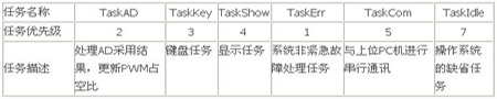
When the system is running, first perform system initialization and create tasks. All newly created tasks are put into a ready state, and the operating system kernel first calls the highest priority task in the ready state. During system operation, the priority of running tasks is always higher than all tasks in the ready state. When a running task is suspended due to waiting for an event or delay, or a higher priority task enters the ready state, the kernel aborts the currently running task and hands the CPU usage right into the ready state. The task with the highest priority. When an interrupt occurs, the system runs the interrupt service routine. When the interrupt returns, the system kernel will perform task scheduling to turn the highest priority ready state task into the running state. For example, an AD sampling completion interrupt occurs during system operation, and the program enters the AD sampling completion interrupt service routine; the interrupt service routine sends an AD sampling result to the mailbox ADResult, because the task TaskAD was previously suspended due to waiting for the mailbox ADResult, so the task at this time The state of TaskAD is changed to the ready state; when the interrupt returns, the kernel performs task scheduling. Since TaskAD is the highest priority task in the ready state (the TaskErr task is always suspended when the system is running normally), regardless of the task that was originally interrupted. What is it, the system will run the task TaskAD, which ensures that the task TaskAD has a fast enough task response speed. After TaskAD executes a loop, it waits for the mailbox ADResult to switch to the suspended state. The kernel performs task scheduling again, calling the highest priority task in the ready state.
5. in conclusion
This paper combines the design of the position sensorless permanent magnet brushless DC motor control system, and determines the development plan of PIC18F452 MCU as the main control device and μC/OS-II as the software platform. The actual development process proves that this development mode can meet the high-performance, low-cost design requirements of the system, and has strong scalability and certain technical forward-looking.
It is worth noting that the use of RTOS in embedded systems enhances the real-time performance of the system and simplifies system software design. At the same time, it also increases the development cost of the system. On the one hand, the operating system will consume certain hardware resources (such as program memory, data memory, timer resources, etc.), which increases the hardware cost of the system; on the other hand, if you purchase a commercial real-time operating system, you need additional software. Spending, even with a free real-time kernel, requires developers to have a deep understanding of the kernel and need to invest considerable effort. Therefore, although the use of RTOS will bring some convenience to the development process, whether or not to use RTOS for specific applications, if used, the specific choice of RTOS is a problem that deserves careful consideration when formulating a system solution.
Tobacco control has been a common global concern, while the traditional tobacco industry gradually, new tobacco has become the new strategic layout of tobacco giants. In this context, the emergence of e-cigarettes has further led to the replacement of traditional tobacco. At present, there are already a thousand different types of e-cigarettes, which have undergone several stages of development. The e-cigarette we are introducing today is the CBD pod systewm, a new type of e-cigarette. In this article we will combine the characteristics of the CBD with a brief analysis of it.
·Anti-anxiety
According to scientific studies,CBD can help depressed patients reduce their anxiety. The use of CBD can help maintain endogenous cannabinoids at a reasonable level, making the patient feel good and happy physically, and without any dependence.
·Anti-ageing
CBD is very powerful in anti-ageing. As a non-psychoactive component of the cannabis plant CBD inhibits the glutamate toxic response of cortical neurons and suppresses excessive oxidative stress, helping the body to achieve anti-ageing effects.
·Anti-inflammatory
CBD reduces the free radicals that cause neurodegenerative diseases and reduces swelling through its anti-inflammatory effects. In addition, CBD stimulates appetite and relieves pain.
China Disposble Vape Pen,E-Cigarette Cbd Vaporizer,Best Disposable Cbd Vape Pen,Disposable Cbd Vape
Shenzhen MASON VAP Technology Co., Ltd. , https://www.masonvap.com