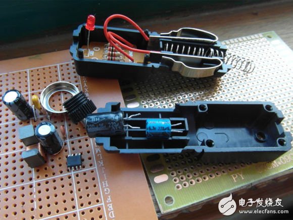
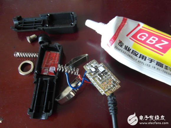
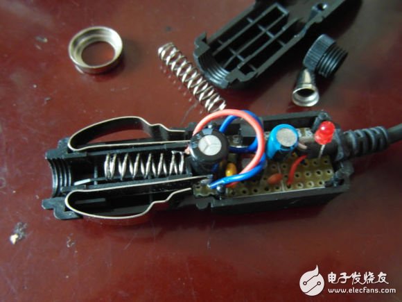
The glare flashlight car charger, there are 4 2k resistors and 1 red LED lamp bead (indicator), one of which is to limit the current of the lamp, the other three resistors are divided in series, take the middle resistor The two ends are used as outputs. In this way, the output is equivalent to a power supply with a voltage of 4v and an internal resistance of 2.67k. In theory, when charging a 3.7v battery, the current is 112μA, charging for one hour, and not enough for a strong light flashlight for one second.
Anyway, this flashlight car charger is a display, used to modify a mobile phone car charger is good, the main parts XL1513E1 last tested no problem, electrolytic capacitors found another 220μ, withstand voltage a 16v, a 6.3v, also There is a USB extension cable (forgetting to take a photo together), you can cut the output
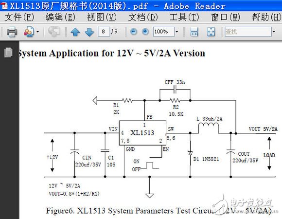
The following is the circuit diagram on the XL1513 data, R1 is replaced by 2.2k, R2 is replaced by 12k, C1 is replaced by 4.7μ monolithic capacitor, D1 is replaced by SS36 (3A60v Schottky diode), CIN withstand voltage 16v, COUT withstand voltage 6.3v, withstand voltage is enough
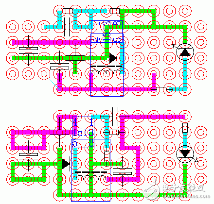
Then design the circuit board, considering the higher frequency, in order to reduce the electromagnetic radiation, the smaller the loop area formed by the 4, 5, 6 and C1, D1 of the XL1513, the better, the shorter the line, the better. Leave a position on the output to see if you can find a USB socket to solder, so the more compact the circuit, the better. First draw one (the top one in the figure below), the sampling part should fly, considering that the sampling part is too close to the input line, and the capacitor is squeezed out, and one is redesigned (the bottom one below), I feel the comparison ideal
Cut the hole plate, weld parts (forgot to take pictures before welding parts), in addition to the two electrolytic capacitors, other parts are directly used for the parts used in the last test, plus a 1k resistor to connect the LEDs of the indicator lights. Because the 2 and 3 feet of the XL1513 are to be suspended, the transparent glue is applied to the corresponding position on the hole plate. When the tin is applied, the transparent glue is still rolled up. When soldering, it is attached to the 2 and 3 feet of the XL1513. A little transparent glue, welded, 2, 3 feet are well isolated
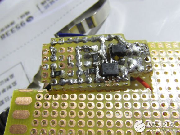
All welding completed
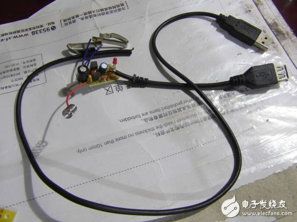
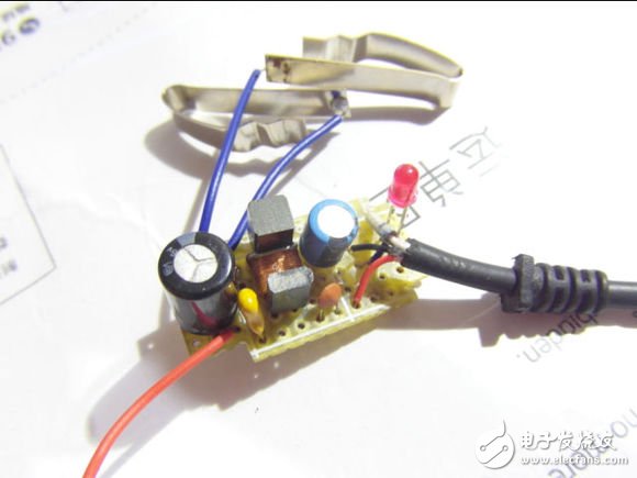
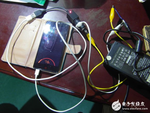
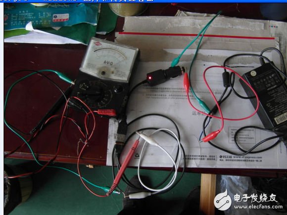
After the welding, check first, no problem, connect the 12v power supply and measure the output. It is the same as the last time to detect the XL1513. Plug in the mobile phone to try charging. No problem, it is more serious when charging. Prepare to add heat sink.
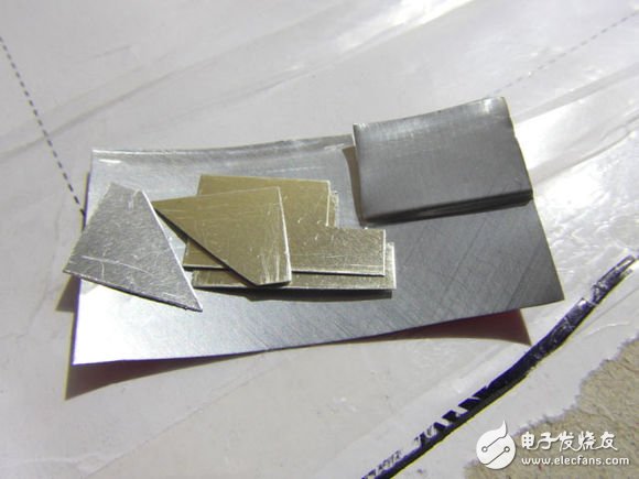
The lid of an aluminum can was cut into small pieces and ready to be wrapped in a jar. Because the heat is serious is XL1513 and diode SS36, especially XL1513, so consider the heat dissipation of these two parts, because the thickness of the two parts is not the same, so the heat sink should also be stepped
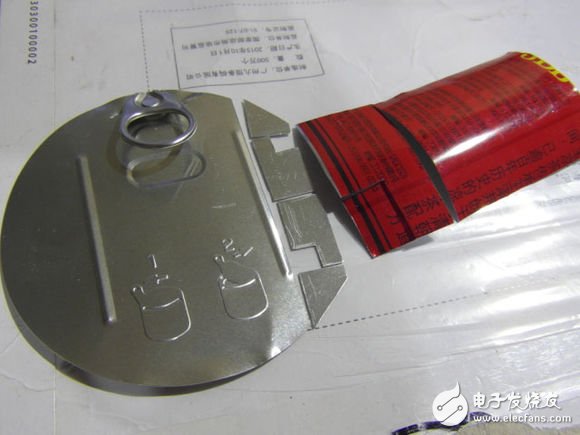
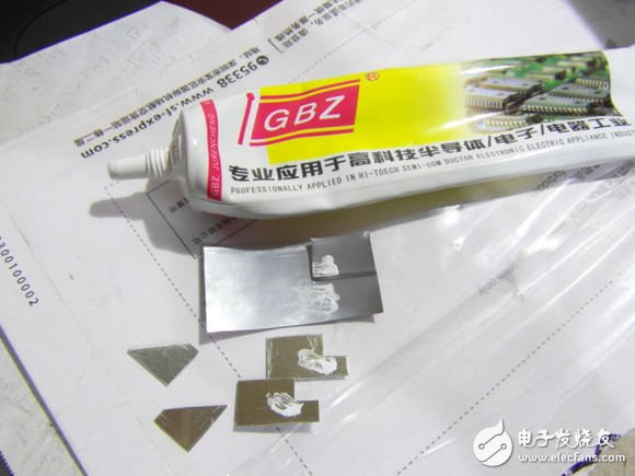
Heated parts are coated with heat-dissipating grease
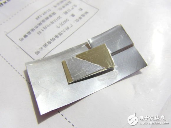
Stack up
package
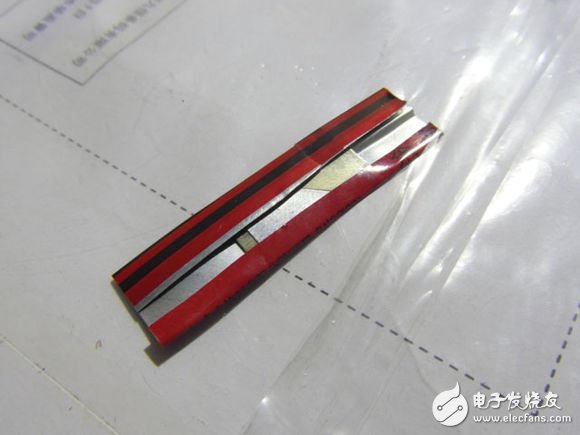
positive
Cut off the excess part of the Jiaduobao jar, apply a little heat-dissipating grease to the parts to be cooled, and stick the other parts in order to avoid touching other parts.
After installing it for a while, I took it down and looked at it. The heat sink is tightly attached to the parts to be cooled.
After the installation, the measured value, even if the output current reaches 2.5A, the output voltage has not dropped, about 5.16v, continue to reduce the load resistance, will enter the short-circuit protection state. Charging test, when the mobile phone power is very small, the input current can reach about 1A, the output current is more than 1.6A, and the input current can still reach 800mA when the mobile phone power is 86%, the output current is about 1.3~1.4A, and the charging speed is obviously better than The original charger is much faster. It seems that this phone does not control the current very much. The maximum current has to be controlled by the charger, or the output voltage is reduced to reduce the current. It seems that the voltage of the charger is about 5.2V when it is no-load. When the battery is fully charged, the voltage should drop to 5v or even lower. Replace the 2.2k resistor with 2.4k. In theory, the output voltage will drop to 4.8v. After the actual measurement, it is close to 4.9v.
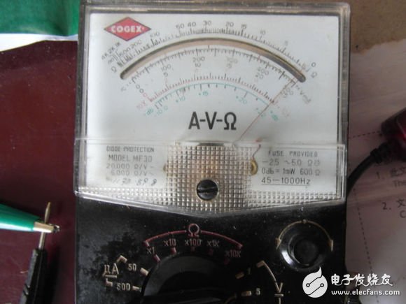
Re-measure the current when charging, when the power of the mobile phone is very small, the input current is more than 600 mA, the screen can reach 700 mA when the screen is on, the output current is 1.1 to 1.2 A, and after the power exceeds 30%, the input current is about 500 mA, and the output current is close to 1 A. After the power exceeds 80%, the input current drops to about 300mA, and the output current is about 600mA. It is no problem to charge the phone. After the voltage is reduced, the heating condition during charging is also significantly improved.
The modification is completed.
Electromagnetic Air Pumps,Magnetic Air Pumps,Air Pump Aquarium,Magnet Air Pump
Sensen Group Co., Ltd.  , https://www.sunsunaquariums.com