Since the introduction of the small power UPS, the transformerless UPS design has experienced more than 20 years of development. Today, most UPSs below 30kVA are transformerless, which means that UPS does not necessarily require magnetic components (transformers or inductors) at the mains frequency (power frequency). This trend of transformerless design is moving toward high power segments because power frequency magnetic components are raw materials and labor intensive industrial products, while high frequency power electronics are technology intensive products.
In general, when technology matures, user value can be increased without sacrificing reliability. Once implemented, technology-intensive design is the preferred leader, and the development of switching power supplies and personal computers has proven this.
For high-power UPS of 30 ~ 200kVA, many manufacturers have mature products without transformer design. In the past decade, high-power insulated gate bipolar transistors (IGBTs) have developed very maturely, using frequency shifts above 10 kHz in high power sections without affecting efficiency.
In addition, some new control technologies make the UPS with transformerless design further reduce switching losses and are therefore more efficient than traditional UPS. For UPSs with power ranges from 200 to 1100 kVA, the biggest challenge is to quickly turn on and off large currents at high voltages without excessive losses or excessive peak voltages.

Figure 1 Schematic diagram of the structure of a conventional UPS and a transformerless UPS
The design principle of traditional UPS
The basic structure of the traditional UPS and transformerless design UPS is shown in Figure 1. The thyristor rectifier used in the conventional UPS considers the fluctuation range of the grid voltage, and the DC voltage (charging voltage) of the three-phase rectified output is generally 500 Vdc or less. The number of batteries in the UPS battery pack is generally 32 to 35. When the battery is discharged, the DC voltage is lower. After the SPWM waveform is converted by the IGBT inverter, the output three-phase AC voltage is only more than 200V. Therefore, the output transformer is required to be boosted to achieve an output of 380V AC power.

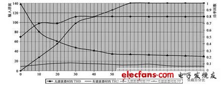
Figure 2 Typical input characteristics of the UPS
To improve efficiency and cost performance, conventional UPSs typically use 6-pulse thyristor rectification, which produces large input harmonic currents and reduces input power factor, which is unacceptable in many applications and is not compatible with some generators. To make the harmonic THDi less than 5% to 10% and the power factor higher than 0.99, a large input inductor and harmonic filter are required. The use of these components will increase cost, weight and size.
In addition, harmonics cannot be reduced and power factor can be increased over a wide range of loads. They are typically effective at load rates above 60%, as shown in Figure 2. At load rates below 40%, the input power factor will be advanced, making it incompatible with the generator. The input power factor also varies with the mains voltage, and the parameter list is only the nominal value.
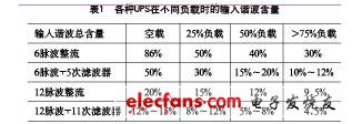
In order to improve the input index, a 12-pulse rectifier and an input filter can also be used. But these will increase size, weight and cost, and reduce overall efficiency. Input indicators can reach THD "5%, PF" 0.95 at full load, but the input indicators will be seriously deteriorated at half load or lower load. The input harmonic content of various UPSs under different loads is shown in Table 1.

For input harmonics, the severity of the impact depends on the particular application and the field environment. For example, a 10% distorted device will cause less voltage distortion at low frequencies than at high frequencies. Without a suitable input filter, the fast di/dt (current spike) generated when the thyristor (SCR) is turned off will cause severe line voltage sag, which in turn affects neighboring devices on the grid.

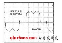
Figure 3 6 pulse wave thyristor rectifier input current waveform
The input current waveform of a typical 6-pulse thyristor rectifier is shown in Figure 3 (oscilloscope real shot). Limit di/dt by input inductance and input harmonic THD"30%.
Our company specializes in the production and sales of all kinds of terminals, copper terminals, nose wire ears, cold pressed terminals, copper joints, but also according to customer requirements for customization and production, our raw materials are produced and sold by ourselves, we have their own raw materials processing plant, high purity T2 copper, quality and quantity, come to me to order it!
LYF Copper Lube Terminals,Ring insulated terminals
Taixing Longyi Terminals Co.,Ltd. , https://www.txlyterminals.com