Infrared remote control is currently the most widely used communication and remote control method. Because the infrared remote control device has the characteristics of small size, low power consumption, strong function, low cost, etc., after the color TV and video recorder, infrared remote control is also used in other small electrical devices such as recorders, audio equipment, airborne machines and toys. . In industrial equipment, in the environment of high voltage, radiation, toxic gas, dust, etc., the use of infrared remote control is not only completely reliable but also effectively isolates electrical interference.
Infrared remote control system:The universal infrared remote control system consists of two parts, transmitting and receiving. The application/decoding dedicated integrated circuit chip is used for control operation, as shown in Figure 1. The transmitting part comprises a keyboard matrix, a coded modulation, an LED infrared transmitter; the receiving part comprises an optical, electrical conversion amplifier, a demodulation, and a decoding circuit.
Infrared simple transmission and reception principle:At the transmitting end, the input signal is amplified and sent to the infrared transmitting tube for transmission. At the receiving end, after receiving the infrared signal, the receiving tube is amplified by the amplifier and restored to a signal, which is the principle of simple transmitting and receiving of infrared.
1 infrared remote control system structure
The main part of the infrared remote control system is modulation, transmission and reception, as shown in Figure 1:
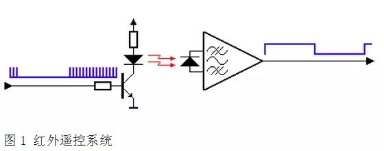
The infrared remote control transmits data in a modulated manner, that is, the data is "ANDed" with a carrier of a certain frequency, which can improve the transmission efficiency and reduce the power consumption of the power supply.
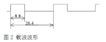
The modulation carrier frequency is generally between 30khz and 60khz. Most use a 38kHz, square wave with a duty cycle of 1/3, as shown in Figure 2, which is determined by the 455kHz crystal used by the transmitter. At the transmitting end, the crystal is divided by an integer. The division factor is generally 12, so 455 kHz ÷ 12 ≈ 37.9 kHz ≈ 38 kHz.
At present, there are many kinds of chips that can realize infrared emission, and different types of codes can be issued according to the selection. Since the transmitting system is generally powered by a battery, this requires that the power consumption of the chip is very low. Most of the chips are designed to be in a sleep state, and work when a button is pressed. This can reduce the power consumption of the chip. The physical impact resistance can not be selected from ordinary quartz crystals. Generally, ceramic resonators are used. The accuracy of ceramic resonators is not as high as that of quartz crystals, but usually a little error is negligible.
The infrared light is emitted through an infrared light emitting diode (LED). The internal structure of the infrared light emitting diode (infrared emitting tube) is basically the same as that of an ordinary light emitting diode. The material is different from the ordinary light emitting diode, and when a certain voltage is applied across the infrared emitting tube, it emits It is infrared rather than visible.

As shown in Fig. 3a and Fig. 3b, the driving circuit of the LED, Fig. 3a is the simplest circuit. When selecting components, pay attention to the switching speed of the triode, and also consider the forward current and reverse leakage current of the LED, generally flowing through the LED. The maximum forward current is 100mA, and the larger the current, the greater the intensity of the transmitted waveform.
The circuit of Figure 3a has a flaw. When the battery voltage drops, the current flowing through the LED will decrease, the intensity of the transmitted waveform will decrease, and the remote control distance will become smaller.
The emitter output circuit shown in Figure 3b can solve this problem. The two diodes clamp the base voltage of the three-stage tube to about 1.2V, so the emitter voltage of the three-stage tube is fixed at about 0.6V, and the emitter current IE is basically not According to IE≈IC, the current flowing through the LED is also basically unchanged, thus ensuring a certain remote distance when the battery voltage is lowered.
2 integrated infrared receiver
The typical circuit of the infrared signal transceiver system is shown in Figure 1. The infrared receiver circuit is usually integrated into one component by the manufacturer to become an integrated infrared receiver. The internal circuit includes an infrared monitoring diode, an amplifier, a limiter, a bandpass filter, an integrating circuit, a comparator, and the like. The infrared monitoring diode monitors the infrared signal and then sends the signal to the amplifier and limiter. The limiter controls the pulse amplitude to a certain level regardless of the distance between the infrared transmitter and the receiver. The AC signal enters the bandpass filter. The bandpass filter can pass the load wave from 30khz to 60khz, enter the comparator through the demodulation circuit and the integration circuit, and the comparator outputs high and low levels to restore the signal waveform of the transmitter. Note that the high and low levels of the output and the transmitter are inverted, in order to increase the sensitivity of the reception. Integrated infrared receiver, as shown in Figures 4a and 4b:
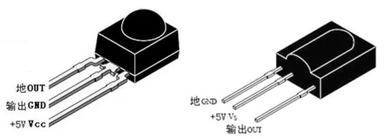
Figure 4a, b
There are many types of infrared receivers, and the pin definitions are different. Generally, there are three pins, including power supply pins, grounding and signal output pins. According to the different modulation carrier of the transmitting end, the receiving head of the corresponding demodulation frequency should be selected.
The gain of the internal amplifier of the infrared receiving head is very large, which is easy to cause interference. Therefore, a filter capacitor must be added to the power supply pin of the receiving head, generally above 22 uf. Some manufacturers recommend connecting a 330 ohm resistor between the power supply pin and the power supply to further reduce power supply interference.
The infrared emitter can be customized from the remote controller manufacturer, or it can be generated by the PWM of the single-chip microcomputer. The home remote control recommends using the infrared emission tube (L5IR4-45) to generate the PWM of 37.91KHz, and the PWM duty ratio is set to 1/3. A simple timer interrupts the PWM to generate a transmit waveform.
Infrared codec analysis1 encoding format
Existing infrared remote controls include two methods: PWM (Pulse Width Modulation) and PPM (Pulse Position Modulation).
The two forms of code are represented by NEC and PHILIPS RC-5, RC-6 and future RC-7.
PWM (Pulse Width Modulation): The duty ratio of the transmitted infrared carrier represents "0" and "1". In order to save energy, in general, the time for transmitting the infrared carrier is fixed, and the duty ratio is changed by changing the time when the carrier is not transmitted. For example, a commonly used TV remote controller uses NEC upd6121, whose "0" is a carrier transmission of 0.56 ms and does not transmit 0.56 ms; its "1" is a carrier transmission of 0.56 ms, and does not transmit 1.68 ms; in addition, for the convenience of decoding, The boot code, the boot code of upd6121 is 9ms for carrier transmission and 4.5ms for no transmission. Upd6121 The total code length is 108ms.
But not all encoders are like this. For example, TOSHIBA's TC9012 has a pilot code of 4.5ms for carrier transmission and 4.5ms for no transmission. Its "0" is 0.52ms for carrier transmission and 0.52ms for no transmission. Its "1" is The carrier transmits 0.52 ms and does not transmit 1.04 ms.
PPM (Pulse Position Modulation): "0" and "1" are represented by the position of the transmitting carrier. It is "0" from the transmitting carrier to the non-transmitting carrier, and never transmits the carrier to the transmitting carrier as "1". The time at which the carrier is transmitted and the carrier is not transmitted is the same, both being 0.68 ms, that is, the time per bit is fixed.
Through the above analysis of the code, it can be concluded that learning the infrared with a certain format of "0" and "1" is very likely to be unsuccessful. That is, the 64-bit, 128-bit that can be learned on the market is necessarily unreliable.
In addition, since the state of the air conditioner is far more than the TV, audio and video, and there is no standard, each manufacturer will do one according to its own format, causing a greater difference. For example: Midea's remote control uses PWM code, the code length is about 120ms; the new remote control also uses PWM code, the code length is about 500ms. Such a big difference, if by the concept of "bit", how many should it be? 64?128? Obviously it is impossible to include such a lengthy code.
1 infrared remote control encoding format
The encoding format of the infrared remote control usually has two formats: NEC and RC5.
Features of the NEC format:
1: Use 38 kHz carrier frequency
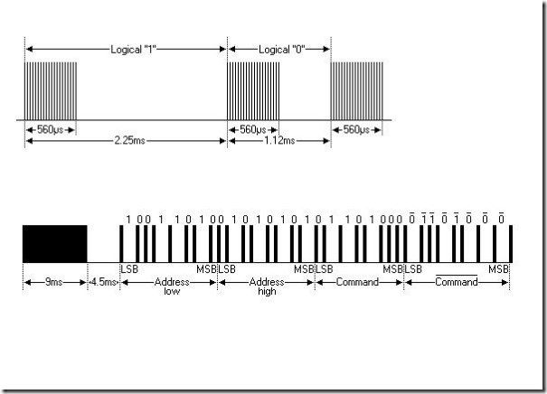
2: Boot code interval is 9 ms + 4.5 ms
3: Use 16-bit client code
4: Use 8-bit data code and 8-bit negated data code
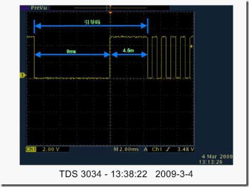
However, it is necessary to reverse the waveform to facilitate analysis:
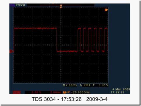
The NEC protocol implements signal modulation by the time interval between bursts (English abbreviated PWM). The logical "0" is composed of a 0.56ms 38KHZ carrier and a 0.560ms carrierless interval; the logical "1" is composed of a 0.56ms 38KHZ carrier and a 1.68ms carrierless interval; the end bit is a 0.56ms 38K carrier.
The following example is the waveform intercepted by the known NEC type remote controller: The identifier of the remote controller is Address=0xDD20; one of the key values ​​is Command=0x0E;
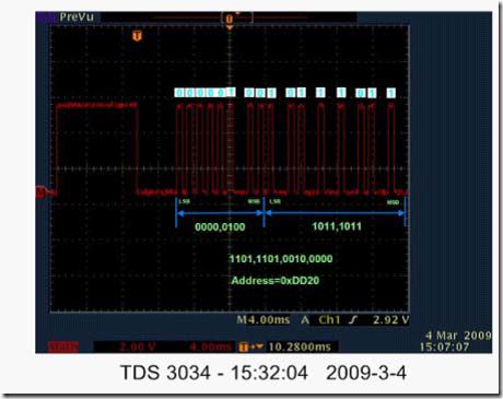
Note: The waveform first sends the low address and then the high address. So 0000,0100,1011,1011 are reversed to be 1101, 1101, 0010,000 hexadecimal DD20; the key value waveform is as follows:
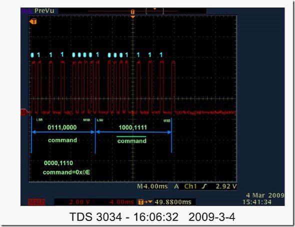
It is also necessary to invert 0111,0000 to 0000, and 1110 to get hexadecimal 0E; also note that the 8-bit key-value code is inverted and then sent again, as shown in Figure 01111000, which is 1000, 1111. The last bit is a logical "1".
The RC5 encoding is relatively simple: Also because the waveform taken from the IR receiver needs to be inverted to facilitate analysis:
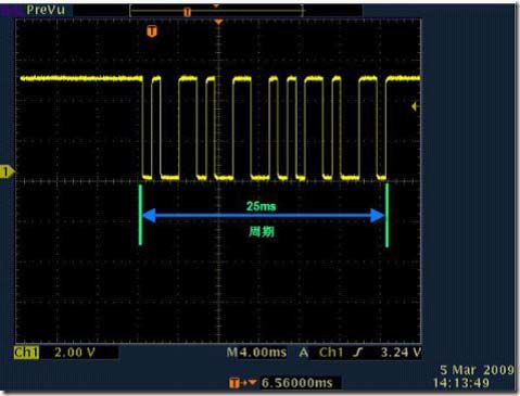
Inverted waveform:
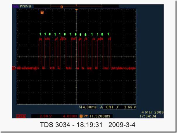
According to the coding rules:
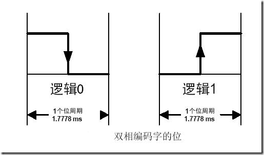
Get a set of numbers: 110, 11010, 001101 according to the code definition:
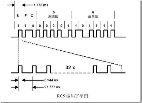
The first bit is the start bit S is usually a logic 1
The second bit is that the field F is usually a logic 1 and in the RC5 extended mode it extends the last 6-bit command code to a 7-bit code (high MSB), which can be expanded from 64 key values ​​to 128 key values.
The third bit is the control bit C. It flips after each key is pressed, so that it can be distinguished whether a key has been pressed repeatedly without releasing the hand or releasing it.
As shown in the figure, the same button repeatedly presses twice to get the waveform. Only the third bit is the opposite logic, and the other bit logics are the same.
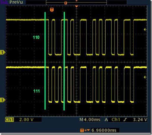
This is followed by five system address bits: 11010=1A, and finally six command bits: 001101=0D.
Digital Display Test Pen ,Power Tester Pen,Voltage Pen,Digital Voltage Tester
YINTE TOOLS (NINGBO) CO., LTD , https://www.yinte-tools.com