TI's TCAN1051HGV-Q1 is a transceiver that meets the ISO11898-2 (2016) high-speed CAN physical layer standard for automotive applications AEC Q100 with data rates up to 5Mbps, I/O voltage range supports 3.5V and 5V MCUs, HBM ESD protection voltage ±16 kV, IEC ESD protection voltage up to ±15 kV, mainly used in all CAN networks, heavy machinery ISO11783 applications, and automotive and transportation. This article introduces the main features of the TCAN1051HGV-Q1, the block diagram and the main features and circuit diagrams of the TCAN10xx series CAN evaluation module.
This CAN transceiver family meets the ISO11898-2 (2016) High Speed ​​CAN (Controller Area Network) physical layer standard. All devices are designed for use in CAN FD networks up to 2 Mbps (megabits per second). Devices with part numbers that include the "G" suffix are designed for data rates up to 5 Mbps, and versions with the "V" have a secondary power supply input for I/O level shifTIng the input pin thresholds and RXD output level. Family of devices comes with silent mode which is also commonly referred to as listen-only mode. AddiTIonally, all devices include many protecTIon features to enhance device and network robustness.
Main features of TCAN1051HGV-Q1:
AECQ100: Qualified for Automotive Applications
Meets the Requirements of ISO11898-2 (2016)
'Turbo' CAN:
All devices support 2 Mbps CAN FD (Flexible Data Rate) and “G†options support 5 Mbps
Short and Symmetrical Propagation Delay Times and Fast Loop Times for Enhanced Timing Margin
Higher Data Rates in Loaded CAN Networks
I/O Voltage Range Supports 3.3 V and 5 V MCUs
Ideal Passive Behavior When Unpowered
Bus and Logic Terminals are High Impedance (no load)
Power Up/Down With Glitch Free Operation On Bus and RXD Output
Protection Features
HBM ESD Protection: ±16 kV
IEC ESD Protection up to ±15 kV
Bus Fault Protection: ±58 V (non-H variants) and ±70 V (H variants)
Undervoltage Protection on VCC and VIO (V variants only) Supply Terminals
Driver Dominant Time Out (TXD DTO) - Data rates down to 10 kbps
Thermal Shutdown Protection (TSD)
Receiver Common Mode Input Voltage: ±30 V
Typical Loop Delay: 110 ns
Junction Temperatures from –55°C to 150°C
TCAN1051HGV-Q1 application:
All devices support highly loaded CAN networks
Heavy Machinery ISO11783 Applications
Automotive and Transportation
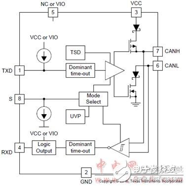
Figure 1. Block diagram of TCAN1051HGV-Q1
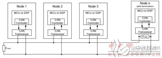
Figure 2. TCAN1051HGV-Q1 typical CAN bus application block diagram
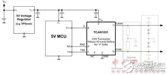
Figure 3. Typical CAN bus application block diagram of the TCAN1051HGV-Q1 using a 5V CAN controller.
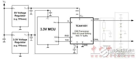
Figure 4. Typical CAN bus application block diagram for the TCAN1051HGV-Q1 with a 3.3V CAN controller.
TCAN10xx series CAN evaluation module
This user guide details the TCAN10xx CAN (Controller Area Network) EVM transceiver operation. TheTCAN10xx CAN EVM is configurable for use with all TI CAN transceiver families: TCAN10xx, TCAN33x, SN65HVD23x, SN65HVD25x, SN65HVD10x0, and SN65HVDA54x by replacing the transceiver andsetting jumpers on the EVM as outlined in this document. This user guide explains the EVM configurations for basic CAN evaluation, various load and termination settings.
The EVM comes with the TCAN1042D CAN transceiver factory installed. The CAN EVM may be reconfigured by a user for use with all TI CAN transceiver families: TCAN33x, SN65HVD23x, SN65HVD25x, SN65HVD10x0 and SN65HVDA54x by replacing the transceiver and setting jumpers on the EVM. EVM has configurations for basic CAN evaluation, various load and termination settings necessary to evaluate CAN transceiver performance.
Main features of TCAN10xx series CAN evaluation module:
Meets the requirements of ISO11898-2
I/O Voltage Range Support 3.3V and 5V MCUs
Ideal passive behavior when unpowered
Bus pins are high impedance (no load to operating bus)
Logic pins are high impedance
Power up/down with glitch free operation on bus
Protection Features
ESD protection of bus pins
HBM ESD ±25kV
IEC ESD ±12kV
Bus Fault Protection ±14V
Under voltage protection on supply pins
TXD (Driver) dominant time out (DTO)
RXD (Receiver) dominant time out (DTO)
Thermal shutdown protection
Characterized for -40°C to 125°C operation
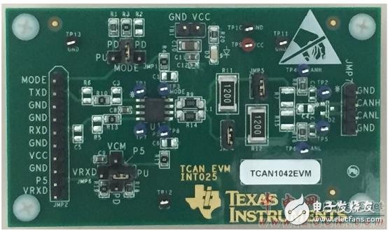
Figure 5. Outline drawing of the TCAN10xx series CAN evaluation module
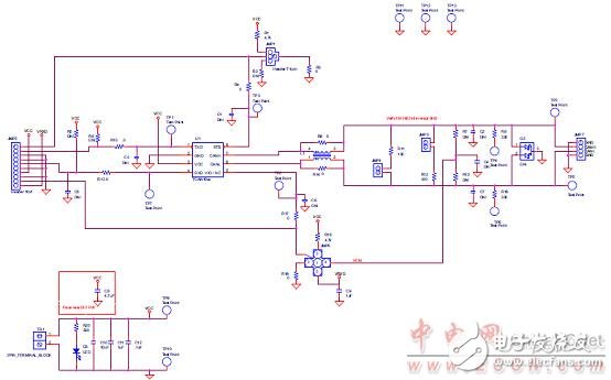
Figure 6. Circuit diagram of the TCAN10xx series CAN evaluation module
Windshield Cell Phone Mount,Car Windscreen Mobile Phone Holder,Car Windshield Cell Phone Holder,Car Windscreen Cell Phone Holder
Ningbo Luke Automotive Supplies Ltd. , https://www.car-phone-holder.com