“ NI TestStand provides a ready-to-use solution that helps us reduce development time with a few key features, and LabVIEW has built-in features necessary to control the hardware of the test system.†-Dillon Glissmann, DISTek Integration Inc.
This article refers to the address: http://
 Challenge :
Develop a flexible automated test set that can test the electronic control unit ( ECU ) of the vehicle system independently or in combination , and allows users to create and maintain test sequences.
 Solution :
Customize NI TestStand software and control PXI- based modular test systems using the NI LabVIEW graphical development environment .
 A global supplier of agricultural, construction and forestry equipment has been working to improve its overall efficiency and effectiveness. To achieve this goal, a test system is needed to help engineers verify and certify new and existing products. The test system needs to be able to meet a range of test requirements and have the flexibility to adapt to hardware changes and future new products. DISTek Integration Inc. is responsible for designing, developing prototypes and deploying an advanced test system that meets these requirements.
 System Components
 We chose National Instruments ' TestStand software and PXI hardware to develop a solution that integrates a wide range of technologies to effectively interact with the ECU . In a complete system, the ECU follows the SAE J1939 protocol and communicates over the CAN bus. The test system uses the NI PXI-8461 CAN DeviceNet module and a custom LabVIEW application to simulate this bus communication. This LabVIEW application acts as a J1939 CAN engine that receives and simulates information from other ECUs .
 For multiple ECU I/Os , multiple NI PXI-6259 data acquisition cards, NI PXI-6527 modules, NI PXI-7833R FPGA modules, NI cRIO-9474, and NI cRIO-9477 modules are used together. Data Acquisition Hardware Measurement System's various control outputs; NI FPGA hardware is used to generate frequency-based signals in real time, such as signals generated by Hall sensors. The system also includes an NI PXI-2569 universal relay switch module to implement matrix switch operation.
 In addition to meeting the I/O requirements of the test unit , NI TestStand combines data acquisition equipment, GPIB, and software-controlled fault buses to maintain and control the power to the system, ECU, and I/O channels. Simulate the voltage changes provided by the on-board battery by adjusting the power consumption of the entire system. Switching the power supply on the ECU layer means that the synchronous start of the entire system can be simulated, while the switching power supply at the I/O channel level can simulate the fault on the channel.
 Adaptable solution
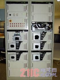
 The test system is scalable and adaptable, and when new products are developed, the hardware can be reconfigured and developed on the original basis. The test system divides each ECU test stand into a functional chassis. Each chassis contains a large number of spare terminals, I/O for system reconfiguration, and an open external connection plug. With the power of the FPGA system, each output channel can be individually controlled, and the channels can be reconfigured for more complex purposes, such as analog encoder signals, pulse width modulation (PWM) signals, or other digital devices that may interact with the ECU . If the test unit changes the channel name, the channel name, scaling and terminal can be easily modified when the operator updates the file in the Excel spreadsheet . Then use a LabVIEW application on a user terminal for data analysis.
 LabVIEW User-Friendly Environment
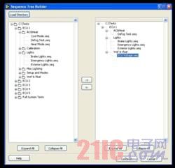
 Creating custom step types in LabVIEW and adding them to the NI TestStand test sequence editor makes it easier to write system tests. These high-level step types allow the operator to perform very simple, friendly interactions with the test system, bypassing some complex operations. This reduces the time it takes to browse the window and creates tests faster.
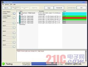
 Using a simple user interface developed in LabVIEW , users can organize a series of tests, save lists for later use, and perform tests in the list while monitoring the system and generating reports. With user-defined display controls, monitoring of analog input signals and CAN communications can be done at any time during test execution. The report is archived and organized according to the status of pass / fail for future reference.
 Benefits of using the NI platform
 As a stand-alone system capable of testing the entire ECU , the system can be used for field testing. Repeated testing with an automated test system is more reliable than using a manual test system, and it is safer because it effectively performs safe interlocking tests on site, which is difficult and dangerous for manual testing by operators.
 The overall flexibility of the test system provides the user with an adaptable and easy to use system for creating and executing tests. NI TestStand provides a ready-to-use solution that helps us reduce development time with key features, and LabVIEW has built-in features necessary to control the hardware of the test system.
 Â

DISTek Integration developed a reconfigurable ECU test system using FPGA technology

Screen capture of the test sequence generator

Test execution user interface
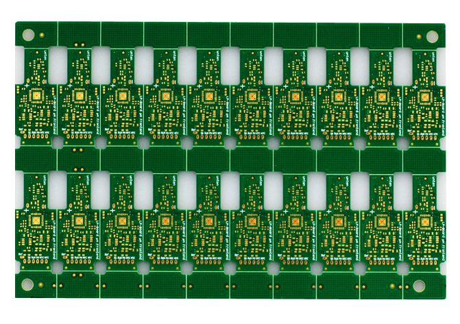
4-layer Medical Treatment PCB Board, Base Material: FR4 TG135. inner/outer copper thickness 1/1.5 oz. Immersion Gold 3U" surface finished. With green colour solder mask and white silkscreen. Board thickness 1.0 mm. Min.line width/Min.line spacing 0.12/0.15 mm. 20-up connect with the routed&v-cut, 100% E-test pass. there are Vias in pad need to be filled with resin and copper cap. Outline Profile tolerance +/-0.1 mm. line width / distance tolerance +/-15%. hole copper 30 um.The medical treatment PCB boards are usually of high precision, strict control of various tolerances required

Medical Treatment PCB Board,Medical Treatment PCB Panel,Medical Treatment Circuit Board,Circuit Board Etching
Orilind Limited Company , https://www.orilind.com