For beginner PLC programmers, the programming of analog input and output modules is more difficult than the use of bit variables for general program control because it is not only program programming, but also involves the derivation of analog conversion formulas. Problems used. Because of the correspondence between A/D and D/A conversions, the S7-200 CPU uses internal values ​​to represent external analog signals. There is a certain mathematical relationship between the two. This relationship is the analog/digital conversion.
For example, when the input analog is set as the input of the current signal, the current signal 0-20mA inside the S7-200 CPU corresponds to the value range 0-32000; but for the 4-20mA signal, the corresponding internal value is 6400-32000. . That may have students do not know how to calculate this 6400? In fact, the digital quantity and current are proportional to each other, and only need to be calculated proportionally. Because the current signal 0-20mA corresponds to the value range 0-32000, the digital quantity corresponding to 1mA is 32000/20=1600, and the digital quantity corresponding to 4mA is equal to 4*1600, which is equal to 6400. (Here is the S7-200 PLC as an example, the same applies to the S7-200 SMART S7-300 400 and so on PLC, but the corresponding digital quantity is different)
Different sensor transmitters are converted by different analog input/output modules. The conversion formula is different. If the selected conversion formula is incorrect, the programmed program must be wrong. For example there are 3 temperature sensor transmitters:
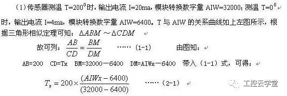
(1), temperature measurement range is 0~200, transmitter output signal is 4~20ma
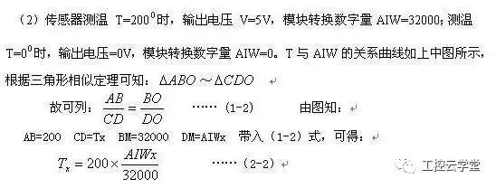
(2), the temperature range is 0~200, the transmitter output signal is 0 ~ 5V
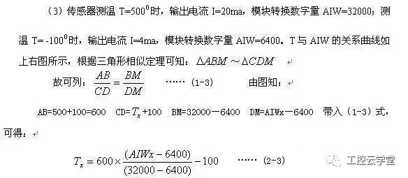
(3), temperature range is -100 ~ 500, transmitter output signal is 4 ~ 20ma
(1) and (2) Two temperature sensor transmitters have the same temperature measurement range, but the output signals are different. (1) and (3) Sensor transmitter output signals are the same, but the temperature measurement range is different. Sensor transmitters use the same analog input module and their conversion formulas are different.
The following uses the parameters of the analog input/output module EM235 of the S7-200 as a basis to derive the conversion formulas of the above three temperature sensors:
For the modules used in (1) and (3) sensor transmitters, the analog input is set to 0 to 20mA current signal, 20ma
The corresponding number of sub-quantities = 32000, 4 ma corresponding to the digital quantity = 6400;
For the (2) sensor transmitter module, the analog input is set to 0 ~ 5V voltage signal, 5V corresponds to digital = 32000, 0V corresponds to the digital amount = 0;
How can the conversion formulas of these three kinds of sensor feeders be derived? This must be helped with the help of mathematics knowledge. Please see below:


The three equations (2-1), (2-2), and (2-3) deduced above correspond to (1), (2), and (3). Then converted to the measured conversion formula. Programmers who program according to the correct conversion formula will get satisfactory results.
New Products
SHENZHEN CHONDEKUAI TECHNOLOGY CO.LTD , https://www.szfourinone.com