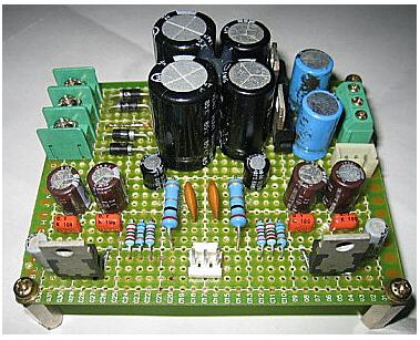
The dot matrix board (universal board/hole board) is a printed circuit board that is covered with a standard IC pitch (2.54mm) and can be inserted and connected as you wish. ". Compared with professional PCB plate making, the hole plate has the following advantages: low threshold, low cost, convenient use and flexible expansion. For example, in the student electronic design competition, the work usually needs to be completed in a few days, so most of the holes are used.
Dot matrix universal experimental small board: 0.7 yuan a dot matrix universal experimental board: 2.2 yuan a piece
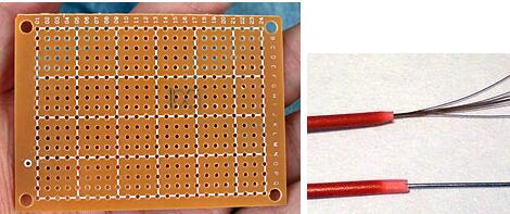
You need to prepare enough thin wires for routing before soldering the dot matrix. The thin wires are divided into single-strand and multi-strand (top right): single-strand hard wires can be bent into a fixed shape, and can also be used as a jumper after peeling; multiple thin wires are soft in texture and appear after welding More messy.
The dot matrix plate has the characteristics of tight pads, which requires high precision of our soldering iron tip. It is recommended to use a pointed soldering iron with a power of about 30 watts. Similarly, the solder wire should not be too thick. It is recommended to select a wire diameter of 0.5 to 1 mm.
Product 4: Guangzhou Huanghua ceramic core 30W long life electric soldering iron (20 yuan a)

Guangzhou Huanghua Electronics Factory's famous brand products, heating up quickly, using the latest ceramic heating body, long service life, can work for a long time, using lead-free long life soldering iron tip is not easy to burn, insulation resistance is greater than 100M, can be soldered with anti-static The device, the handle has a power indicator function, which is more convenient to use.
Second, the basic steps of manual welding operationsMaster the soldering iron temperature and soldering time, and choose the proper soldering iron tip and solder joint contact position to get a good solder joint. The correct manual soldering process can be divided into five steps:
Step 1: Prepare for welding (figure (a))
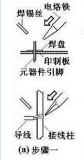
Hold the wire in the left hand and hold the soldering iron in the right hand to enter the ready-welded state. The tip is required to be clean, free of oxides such as slag, and coated with a layer of solder on the surface.
Step 2: Heating the weldment (Fig. (b))
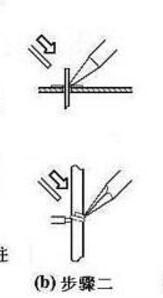
The tip of the iron is placed at the junction of the two weldments to heat the entire weldment for approximately one to two seconds. For soldering components on a printed board, care should be taken to allow the soldering iron tip to simultaneously touch two soldered objects. For example, the wires in Figure (b) and the terminals, component leads and pads should be uniformly heated at the same time.
Step 3: Feed the welding wire (Fig. (c))
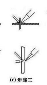
When the welding surface of the weldment is heated to a certain temperature, the solder wire contacts the weldment from the opposite side of the soldering iron. Note: Do not send the solder wire to the soldering iron!
Step 4: Remove the wire (figure (d))
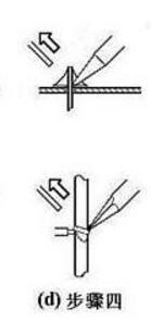
When the wire melts a certain amount, immediately remove the wire from the upper left 45° direction.
Step 5: Remove the soldering iron (Figure (e))
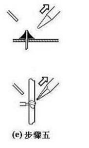
After soldering the solder pad and the soldering portion of the soldering piece, remove the soldering iron to the upper right 45° direction to end the soldering. From the third step to the end of the fifth step, the time is also about 1-2 seconds.
Third, the welding attention points1. Keep the tip clean
2, increase the contact area to accelerate heat transfer
3, heating depends on the solder bridge
4, the soldering iron evacuation has to pay attention to
The withdrawal of the soldering iron should be timely, and the angle and direction of the evacuation are related to the formation of the solder joint.
5, can not move before the solder solidifies
6, the amount of solder should be moderate
7, the amount of flux should be moderate
8, do not use a soldering iron tip as a tool to transport solder
1 The shape is approximately conical and the surface is slightly concave, which is in the form of a slope. It is centered on the welded wire and is symmetrically formed into a skirt shape. The surface of the virtual solder joint tends to bulge outward and can be identified.
2 On the solder joint, the solder joint surface is concave and natural transition, the junction between the solder and the weldment is smooth, and the contact angle is as small as possible.
3 The surface is smooth and has a metallic luster.
4 No cracks, pinholes, slag inclusions.

Shenzhen Linx Technology Co., Ltd. , https://www.linxheadphone.com