Industrial control, factory automation and PLC (Programmable Logic Controller) are mature technologies that can effectively save time, materials, energy and money. But where do you start? Designing a fully automated factory is a huge project and may be abandoned before the project is started.
This reminds us of an explorer in Africa many years ago. When he asked a local tribal man: "How to eat an elephant?", the man looked at the explorer in surprise and replied: "We eat elephants. Just like eating anything else, one bite at a time." Like other large-scale system development, industrial control systems can be divided into many small-scale circuits. Now we begin to discuss these subdivided circuits.
Process control flowThe assembly line is a fairly new invention and creation in human history, and similar innovative solutions have emerged in many countries during the same period. We will list a few examples of them and explain how to evolve to a complete automated factory.
Samuel Colt (American gun manufacturer) demonstrated a universal part in the mid-19th century. Early guns needed to independently manufacture the parts of each gun and then assemble them. Mr. Colt showed the common parts of 10 guns, and then randomly grabbed these parts from the box and assembled a gun. In the early 20th century, Henry Ford further expanded its mass production technology. He uses fixed assembly plants and uses trucks to transport parts between plants. Employees only need to understand very little assembly knowledge, and only perform these operations in future work. In 1954, George Devol applied for US patent 2,988,237, which marked the birth of the first industrial robot, which was named Unimate. In the late 1960s, General Motors® used PLC (Programmable Logic Controller) to assemble automatic transmissions for automobiles. Dick Morley, known as the father of PLC, produced the first PLC for GM. His US patent 3,761,893 is the basis of many current PLCs (for detailed information about the above four inventors, please refer to:; for related patents, please refer to: http://patft.uspto.gov/netahtml/PTO/srchnum .htm).
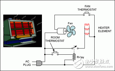
How simple can process control be? Figure 1 shows a common household heater.

Figure 1. Household electric heater, a simple process control example.
The heater components are sealed in a container to simplify system communication. This concept can be extended to remote-controlled thermostat heaters with a communication distance of about a few meters, and voltage control is usually adopted.
Now, we can consider a small and simple process control system. What are the necessary components in the factory shown in Figure 2?

Figure 2. Remote communication of the factory
The impedance, EMI, and RFI (Electromagnetic and Radio Interference) of long-distance transmission lines make the implementation of voltage control schemes very difficult. In this case, the current loop is a simple and effective solution. According to Kirchhoff's law, the current at any point in the current loop is equal to the sum of the currents at all other points in the loop, which can offset the influence of the transmission line impedance. Due to the low loop impedance and bandwidth (a few hundred ohms, <100Hz), EMI and RFI spurious pickup is minimal.
Basic Principles of PLCThe application of the current control loop started in the teletypewriter in the early 20th century. The 0-60mA loop was first used, and later changed to the 0-20mA loop. The PLC system was the first to join the 4-20mA loop. The 4-20mA current loop has many advantages. Using 4mA as the lowest communication current, this fault can be easily detected when the transmission line is disconnected (open circuit). Only two wires are needed to power the remote sensor, about 3.5mA. The 4-20mA loop can use analog communication or digital communication.
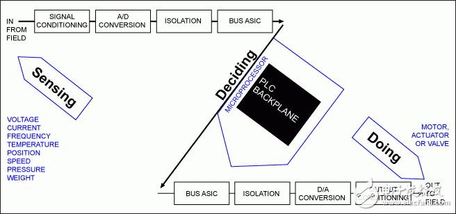
In the traditional discrete device design, careful calculation is required, and the circuit takes up a lot of space. Maxim has introduced several 20mA devices that can greatly simplify system design. We first consider the typical PLC function, as shown in Figure 3.

Figure 3. Simplified block diagram of PLC
PLC is used to complete a certain job or task. We first detect a physical parameter, process it and make decisions, and then order a physical device to act. According to this model, the lower left frame shows the signal conditioning output, which can be the MAX15500/MAX15501 integrated circuit.
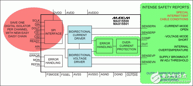
MAX15500/MAX15501 allow selection of short-range voltage control or remote current control. It can be seen from Figure 4 that in addition to the basic communication functions that are available in the traditional discrete solution, new monitoring and protection functions have been added to the device.

Figure 4. MAX15500/MAX15501 output conditioner series products. The device functions include: ±12V load sensing output for 1kΩ, ±24mA current supply for 750Ω, 14-bit settling time of 100µs, and 12-bit settling time of 40µs.
Factory wiring is affected by factors such as movement, vibration, etc., which may cause an open circuit or short circuit with other connectors. In order to ensure equipment and personal safety, safety monitoring is required. When a cable fails, there will be a period of time before the system completely fails. The MAX15500 series can intelligently monitor and manage different failure conditions.
Taking into account the extreme EMI, RFI, and power surge conditions of the factory, any monitoring measures must be reliable and free from interference from the external environment. The MAX15500 series includes a minimum open circuit and short circuit timeout period of 260ms. This time period is sufficient to avoid false alarms caused by monitoring noisy environments, and it is also sufficient to capture short-term cable faults. In addition, the device will latch the fault and trigger an independent hardware interrupt pin alarm, allowing the processor to quickly respond to cable short-circuit faults. After receiving the interrupt, the processor can read the contents of the MAX15500 register, obtain accurate fault information, and clear the fault interrupt. In addition to monitoring the condition of the cable, the device also provides other safety functions, such as monitoring the environment by detecting the chip temperature to see if the environment is overheated. Adjustable power drop detection threshold is critical to reliable system design. Power supply voltage detection threshold can be adjusted in the range of ±10V to ±24V, with a level difference of 2V.
In order to ensure system safety, the MAX15500/MAX15501 output also has overcurrent protection, short-to-ground protection, and overvoltage protection up to ±35V. To meet customer needs, MAX15500/MAX15501 provide programmable over-range capability. Some users use 105% or even 120% of the full scale for testing or emergency operations (the system may be due to a partial failure or strong noise environment). MAX15500/MAX15501 are available in a 32-pin, 5mm² TQFN package with exposed pads to improve heat dissipation.
The MAX15500/MAX15501 output conditioner complies with the HART® standard. The HART (High Speed ​​Addressable Remote Sensor) protocol can carry two-way digital signals on the 4-20mA control line, similar to the Bell 202 at 1200 baud rate for fixed telephone calls protocol.
MAX15500/MAX15501 also have an independent SPIâ„¢ bus, which reduces the need for optoisolators for electrical isolation. The device uses a special self-timed SPI interface and supports the daisy chain protocol. When multiple SPI devices need to be controlled through electrical isolation, this mode helps reduce the need for control lines and isolation optocouplers.
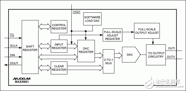
Integrate more functions on a smaller PCB (PC board)Designing discrete, selectable voltage (unipolar and bipolar) or current output regulation circuits is a very challenging task, especially when the designer understands the need to control the full-scale variable gain, for unipolar and bipolar When multiple reset levels of the polarity voltage setting, 0mA and 4mA circuits are required, the complexity of the system will be further understood. Figure 5 simplifies the design of these functions, because these functions have been integrated in the MAX5661 current and voltage output DAC.

Figure 5. Simplified functional block diagram of MAX5661
MAX5661 solves the problem of discrete solution design with its programming function. The following parameters can be easily selected:
The output voltage
Unipolar range: 0 to +10.24V, ±25%
Bipolar range: ±10.24V, ±25%
Current output
Unipolar low range: 0 to 20.45mA
Unipolar high-end range: 3.97mA to 20.45mA
Full-scale output gain
Adjust up to ±25% over-range with 10-bit resolution or interval
Asynchronous reset or clear, or preset to 16 digits
These functions provide design flexibility. When used as an analog power supply, the output voltage range is ±13.48V to ±15.75V; when current is output, the output voltage swing is: +13.48V to +40V. The differential voltage output can be remotely detected through the load/induction detection of the voltage output amplifier. Fault output interruption indicates open-circuit current output, short-circuit voltage output or status clear. This function is driven by current-limiting voltage output; for current output, the differential pressure detector monitors the current output beyond the specified range. The /LDAC pin is used to control asynchronous DAC updates and multi-DAC synchronization systems.
All the above functions are integrated in the MAX5661 10mm x 10mm LQFP package.
Use voltage and current conditioning to provide multiple PLC outputsObviously, multiple MAX5661 16-bit devices can be used to provide other additional functions. However, other solutions can be considered for PLC systems that require low resolution and low cost. Maxim provides DACs with a resolution of 6 to 16 bits, with more than 2500 A variety of different types of devices. The channel options for this series of products include: 1 to 4 channels, 8 channels, 16 channels and 32 channels. Communication interfaces include parallel, high-speed SPI and I²C serial bus. In addition, you can also choose fast settling time (< 1µs), small size (SOT23, QFN, µMAX®), and higher precision (≤ 1 LSB INL).
Maxim's recent high-precision DAC series include MAX5134–MAX5137 and MAX5138/MAX5139. These DACs include six optional buffered voltage outputs. All devices use a single power supply from +2.7V to +5.25V and provide a 3-wire SPI/QSPI™/MICROWIRE™/DSP compatible serial interface.
MAX5134–MAX5137 are pin-compatible and software-compatible 16-bit and 12-bit DACs. MAX5134 is a four-channel 16-bit device with an INL of ±8. MAX5135 is also a four-channel DAC with a resolution of 12 bits and INL of ±1; MAX5136 is a dual-channel 16-bit device with INL of ±8; MAX5137 is a dual-channel 12-bit device with INL of ±1. Each DAC is available in an ultra-small size (4mm²), 24-pin TQFN package, and operates in an extended industrial temperature range from -40°C to +105°C.
The MAX5138/MAX5139 are single-channel, pin- and software-compatible DACs, available in a small (3mm²), 16-pin TQFN package. MAX5138 is a 16-bit DAC with a typical INL value of ±2; MAX5139 is a 12-bit DAC with a typical value of ±0.25.
The high-performance MAX5134–MAX5139 have a built-in 10ppm/°C high-precision reference, and an external reference can also be used to support rail-to-rail output. A hardware input pin is used to control the output settings of the DAC, and the DAC output can be set to 0 or an intermediate value at power up or reset. This feature provides additional protection for valve drive or other transmitter applications that need to be closed when power is applied. The hardware load DAC (/LDAC) pin supports the simultaneous update of multiple DACs. The serial interface provides /READY output to simplify the control of multiple MAX5134–MAX5139, MAX15500/MAX15501 and MAX5661 devices when they are connected.
For cost-effective 4-channel output PLC applications, you can choose the MAX5135 four-channel 12-bit DAC and the four-channel MAX15500 output conditioner.
in conclusionThe high linearity and output conditioning capabilities of Maxim DACs make these devices ideal for high-precision control and instrumentation. Maxim devices provide designers with a simple and wise choice that can eliminate the complexity and large-scale design troubles of discrete circuits. Simplified design means that voltage or current drive can be selected at will, allowing busy engineers to focus on the key parts of system design, reducing waste, providing more effective high-precision control, and improving our environment.
The 2kw FM Transmitter is a compact 3U, versatile and economical unit with an R.F. output in excess of 2kW, combined to provide 2kW O/P, with enough `head-room` for high reliability in extreme temperature and VSWR conditions. The FM transmitter offers overall efficiency of greater than 76%, which translates to lower heat dissipation and therefore the higher the reliability.
2000W Fm Transmitter,2000W Fm Stereo Broadcast Transmitter,2000W Fm Transmitter For Radio Station,2Kw Fm Radio Broadcast Transmitter
Anshan Yuexing Technology Electronics Co., LTD , https://www.yxhtfmtv.com