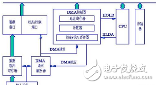
There are two forms of data transfer on the bus. One is Programmable Input/Output (PIO) and the other is Direct Memory Access (DMA).
1, PIO
When using PIO, the CPU is the main module, and the reading of data on the bus is directly initiated by the software program running on the CPU, and the transmitted data must enter the CPU (as described in the first and second below).
1. The software instruction or the data already stored in the CPU data register is sent to the target controlled module;
Second, or read a data in the target controlled module, put it in the data register of the CPU.
For example, you need to transfer data from module A--- to module B, and the software breaks down this task into two PIO operations.
The first step: reading data from module A and storing it in the data register of the CPU;
Step 2: Write the data stored in the CPU data register to module B.
2, DMA
Since the clock frequency of the system bus between the link chip and the chip is much lower than the clock frequency inside the CPU, reading and writing a large amount of data with the PIO is a very inefficient way to take up the processing power of the CPU. Therefore, special hardware is needed to assist in the execution of data transfer between the chip and the chip or between the module and the module. This is DMA.
At this point, the software only needs to transmit the data request to use the PIO to notify the DMA hardware, and the DMA hardware performs the data transmission as required. During this time the CPU continues to do other work. After the DMA hardware has performed the data transfer task, the software is notified by an interrupt signal or by writing a specific value to a specific address of the main memory. 
A DMA hardware typically includes multiple DMA channels. Each channel is generally used for data transmission between a pair of modules, and the channels are independent of each other.
The DMA descriptor is used to specify how the data block is transferred. A DMA descriptor includes at least the source address (SA) of the data transfer, the destination address (DA), the amount of data to be transferred, and the transfer size per bus transfer. Some DMA modules require software to store the data structure of the DMA descriptor in main memory. The software can be very efficient in establishing DMA descriptors when using the benefits of this method. Before the DMA performs a DMA data transfer task, the DMA first uses the DMA method to read the DMA descriptor stored in the CPU main memory into the DMA module.
DMA divides the transmission of one block into two steps.
The first step: reading data from the controlled module of the source address;
Step 2: Write the read data to the controlled module of the destination address.
According to the DMA descriptor, the DMA can automatically update the source address and the destination address to the next data block address after transmitting a data block, and then the DMA starts transmitting the next data block, and continues to transmit the order of magnitude of the actual required transmission. . Suppose that the amount of data that a DMA starts to transmit is 128 bytes, and the data block transmitted each time is 16 bytes. In order to complete the data transfer specified by this DMA descriptor, the DMA automatically performs 8 bus reads and 8 bus writes. These transfer paths do not pass through the CPU
Function description
The socket is ordinary converter,with two output 5V2A power USB power supply at the same time,can be very convenient in use electrical appliances and recharge the equipment at the same time,such as digital products like Iphone Ipad,MP3,MP4 etc.The charge apply to full range of international AC output,no-load power consumption less than 0.3W,with short circuit,overload,over-voltage protection,can be convenient for your life and save more energy
Timer Control Time Adgustment
1.Press the power switch 1 time,the 1HOUR LED will light on.The Timer into ON mode,USB and control socket output ON .
2.Continuously press the power switch the LED light on,the Countdown mode and LED light on will cycle change from 1HR,2HR,4HR,6HR,8HR,10HR.
3.Choose you need countdown time mode,the mode LED will lighto on,start countdown until countdown time finish,the control output and USB change to OFF
4.Then the countdown is start,The Time indicate LED will from high to low auto change until Countdown finish off.
Failure analysis:
1.check whether the power supply connection is good
2.check whether the USB cable is loosen
Warning Note:
1.Use indoor and dry location ONLY
2.The load max does not exceed 15A 3600W
3.This product does not convert voltage please do not miss use DO NOT exceed the maximum loading of 3600 Watts 15A
4.Always have earth connection for safety reason
5.If in doubt please consult with a qualified electrician
USB charger socket, USB socket, USB plug, USB plug socket
NINGBO COWELL ELECTRONICS & TECHNOLOGY CO., LTD , https://www.cowellsocket.com