In the context of the development of a gun follower system, in order to further improve the system accuracy, the composite control system model and the partition PID algorithm are introduced firstly. The principle of the double motor backlash and the dynamic system structure are discussed in detail, and the simulation model is established. . Finally, the madab simulation shows that the simultaneous use of the partitioned PID algorithm and the dual motor anti-backlash technology can greatly improve the tracking accuracy of the servo system while ensuring the stability of the system.
As we all know, the classic PID is very commonly used in the control of the follow-up system because of its simple algorithm. However, since the ratio, integral and differential of the classical PID algorithm are always constant, this makes its control effect not very good. The effect, while using the partitioned PID control, can adopt corresponding algorithms in different sections according to actual needs, which can greatly improve the stability of the system. In addition, there is a backlash in the gear of the servo system, which can be well overcome by the dual motor backlash technology, and the gun has higher tracking accuracy, smaller error and better robustness.
1 Artillery follower system structure and partition PID control algorithm
1.1 Composite control system structure
The system uses a composite control structure and uses both feedback and feedforward control. Based on the position loop partition PID controller, speed and acceleration feedforward are introduced. The composite control block diagram is shown in Figure 1.
At the beginning, the motor starts to run. At this time, the difference between the output angle and the input angle is the largest. It is in the three zones. The system accelerates with the maximum angular acceleration and then approaches the equilibrium point at the maximum angular velocity. At this stage, Kp should be increased and Kd should be decreased. At the same time, in order to prevent the output value from being too large, Ki should be increased.
When the system is in the second zone, PI control is selected, in which the actual angular velocity is brought closer to the ideal angular velocity.
In the one zone and the zero zone, the actual position gradually approaches a predetermined value, and Kp should be reduced to increase the Kd and Ki in order to suppress overshoot.
When the system is in the community. The system static difference is already small enough, and only P control is required.
2 Double motor backlash principle and digital simulation
2.1 Double motor backlash principle
2.1.1 Nonlinearity of backlash and its effect on system stability
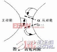
Ideally, the gear shifting device in a servo system should have a linear relationship between its input and output. In practice, however, due to the presence of errors in the machining and use of the gears, and in order to compensate for dimensional changes caused by temperature and elastic deformation, there is always a certain backlash between the pair of intermeshing gears. Figure 2 shows the gears. The gap in the mesh.

When the direction of the driving wheel changes, the driven wheel remains in its original position, and the position of the driven wheel begins to change until the entire backlash 2α is completed. It is this gap that makes the ideal linear drive a non-linear transmission process that affects system stability.
2.1.2 Principle of double motor backlash
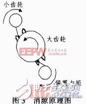
In order to eliminate the influence of this nonlinear drive on system performance, this paper uses a dual motor drive method to eliminate backlash. The essence of this method is that in the process of starting and reversing the transmission system, the output gears of two sets of completely identical speed reduction mechanisms are respectively attached to the opposite meshing surfaces of the main shaft gears, so that the main shaft gears are subjected to the biasing moment. Can not swing back and forth in the backlash, so as to eliminate the gear gap, the principle of backlash is shown in Figure 3.

In the one-way transmission, the two drive stage pinions rotate in the same direction, so they must be closely attached to the two gear faces in the same direction of the output stage large gears, and are driven together by the elastic force. When the system needs to be commutated, through a certain control method, through the motor output torque in the opposite direction, one of the drive stage gears continues to be in close contact with the original gear surface of the output stage gear, and the other drive stage gear performs The reversing direction is in close contact with the reverse gear surface of the output stage gear, so that the elastic force applied to the output stage gear by the two drive stage gears is opposite in direction, thereby preventing the output stage gear from swinging without being subjected to a torque. Then the first drive stage gear is quickly reversing and fits to the reverse gear face of the output stage gear for unidirectional transmission in the opposite direction. In addition to the commutation process, there is also the influence of the backlash factor in the starting of the system, and the anti-backlash principle of the dual motor drive system for the starting process is the same as the commutation process.
2.2 Establishment of simulink simulation model
2.2.1 Block diagram of double motor anti-backlash servo system
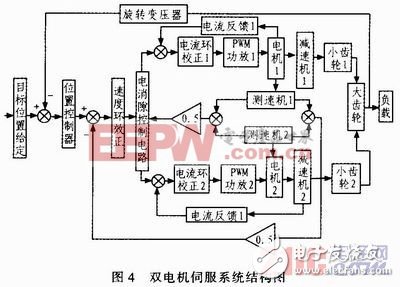
The two-motor drive system is driven by two motors with the same parameters to drive a pinion of the same modulus. According to a symmetrical structure, the pinion gear meshes with the large gear to jointly drive a large gear with a load to rotate. On this basis, a block diagram of the two-motor servo system controlled by the current loop, the speed loop and the position loop three loops can be obtained, as shown in Fig. 4.

The current loop and the speed loop are inner loops. When some internal parameters are disturbed, current feedback and speed feedback can suppress in time, which has little effect on the system; the position loop is an outer loop, which is directly related to the dynamics of the system. Track performance and steady state accuracy. The anti-backlash control circuit is used to form a suitable bias current to achieve backlash.
2.2.2 Simulation model of double motor anti-backlash servo system
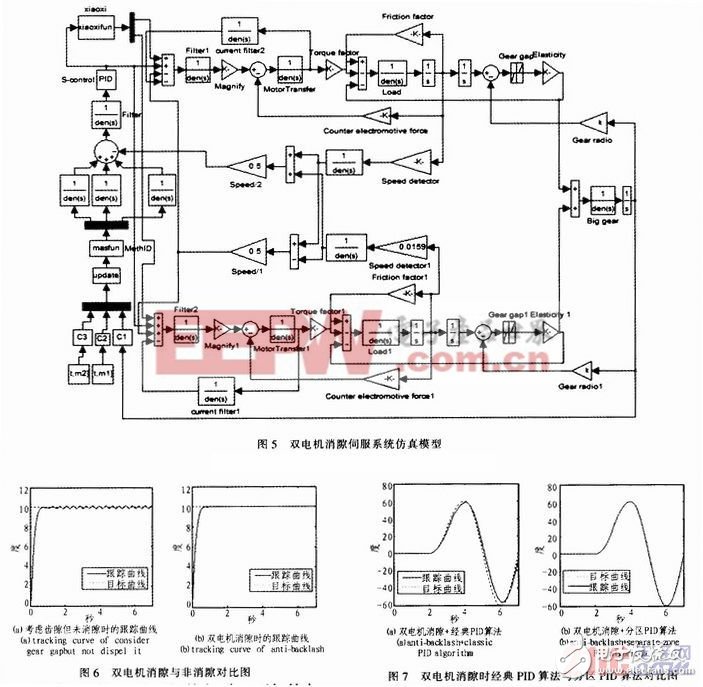
According to the structural block diagram of the servo system, a simulation analysis model of the dual motor anti-backlash servo system based on the partition PID control can be obtained, as shown in Fig. 5.

The feedforward control quantity of acceleration and speed obtained by the working space is input by C2 and C3 modules respectively; the feedback quantity of the position obtained by the position loop is input by C1; after being integrated, it is input to the updata module, which is mainly used to generate the user has set The fixed data, that is, the motion and parameters set by the user in the GUI interface; methID is the position controller, and the partition PID control is performed by the position error.
S-control is a speed controller that receives feedback from the speed loop. Its input is voltage and the output is current.
The xiaoxi module is a backlash control unit whose input is current, forming a backlash bias current, and the output is applied to the current reference terminals of the two motors to achieve electrical backlash.
The Magnify module represents a power amplifier that is used to drive current amplification. The motor armature model of the Motor transfer module forms a feedback of the current loop. The Torque factor module represents the torque factor and the output is the motor torque. After the load reducer, the feedback here passes the speed detector output slope of the Speed ​​detector module, converts the speed into voltage, and then passes the differential feedback control formed by the module Speed/1 and Speed/2 to ensure the synchronous operation of the two motors. Finally arrive at the S-control, forming a feedback of the speed loop.
The reducer drives two pinions of the same modulus, and the output of the pinion is the position amount.
The Gear gap model can set the backlash size.
The ElasTIcity module is a model for transmitting torque between large and small gears, and the gears are in contact by elastic forces. The input of this module is the position quantity, and the output is the torque. This torque is used to drive the big gear large gear to drive the load.
2.2.3 Analysis of simulation results
Fig. 6(a) shows the tracking curve considering the backlash but no backlash when the fixed point is shot. Fig. 6(b) is the tracking curve after considering the backlash and using the double motor to eliminate the gap, wherein the backlash is chosen to be 3 mil.
Comparing Fig. 6(a) with Fig. 6(b), it can be seen that when there is no backlash, the system is unstable, and the tracking error oscillates within ±0.2°, which makes it impossible to achieve high-precision tracking. After using double motor backlash, the tracking error is almost Reducing to 0° significantly eliminates residual oscillations at fixed-point guns.
Fig. 7(a) shows the tracking curve of the double motor backlash + classic PID algorithm for sinusoidal gun, and Fig. 7(b) shows the sinusoidal tracking curve of the + partition PID algorithm for double motor backlash.
7(a) and 7(b) show that the tracking error of the partitioned PID algorithm is almost zero when the sinusoidal gun is used. The classical PID algorithm has obvious delay and large error.
3 Conclusion
The system uses partitioned PID control + dual motor backlash technology. The simulation results show the feasibility and effectiveness of this combination method. Not only ensures the rapidity and stability of the system tracking, but also the tracking accuracy has been greatly improved.
Solutions,Networking Solution,Network Solutions,Beyond Networking Solution
Huizhou Fibercan Industrial Co.Ltd , https://www.fibercannetworks.com