Four-rotor aircraft is a multi-rotor UAV that can perform vertical take-off and landing, hovering, yaw and other complex actions. Therefore, its application prospects in the military and civilian fields are very optimistic [1], but its own system complexity and Problems that are vulnerable to outside aerodynamics and uncertainties have plagued researchers.
In response to these problems, researchers have studied the control methods and filtering algorithms of the quadrotor aircraft system model. The classic PID algorithm is a control method that does not depend on the system model. The method is simple in structure and mature in theory [2], but the parameter setting is more complicated. The backstepping method in literature [3-4] has good tracking effect and fast response to nonlinear systems, but its robustness is poor and its anti-interference ability is weak, and an accurate system model needs to be established. The literature [5] uses the synovial control method to control the quadrotor. Although the synovial control method has better robustness than the backstepping method, none of these algorithms can estimate and compensate the system disturbance in real time. Each channel is decoupled. When the external interference is large, the control effect is not ideal. Although the selection of the control method can reduce the dependence on the four-rotor model and ensure the relative stability of the internal system, it is indispensable for the research of the filter algorithm to realize the safe flight of the quadrotor in a complex environment.
The paper [6] uses particle filtering to estimate the attitude of the aircraft, which shows a strong superiority in nonlinear systems, but it has a large amount of calculation, and it is difficult to meet the real-time control effects of the quadrotor. The literature [7] uses the complementary filtering to fuse the data of the quadrotor. According to the different characteristics of the gyroscope and accelerometer sensors, the algorithm combines the advantages of the two to get better data, but it has the same system as the particle filter. Delay problem. Literature [8-9] proposes a pose estimation algorithm based on Kalman filter, which can effectively filter out-boundary noise and ensure the accuracy of the acquired data. However, when the system filtering deviation is large, the phenomenon of filter divergence occurs, resulting in the system can not be normal work.
Combining the above issues, this paper proposes an improved EKF auto-disturbance rejection control method, which uses an auto-disturbance rejection controller to control the attitude of the aircraft, and filters the noise-inhibited attitude by the improved EKF to make the flight attitude more stable and effectively improve the system's Stability and immunity to interference.
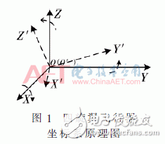
1 Four-rotorcraft dynamics modelIn order to obtain a mathematical model of a quadrotor, first two coordinate systems are established: the inertial coordinate system E (OXYZ) and the body coordinate system B (OX'Y'Z'). Its center of gravity and center of mass coincide with the aircraft origin O (O'), as shown in Figure 1.
Then the four-rotor dynamic model is [10]:
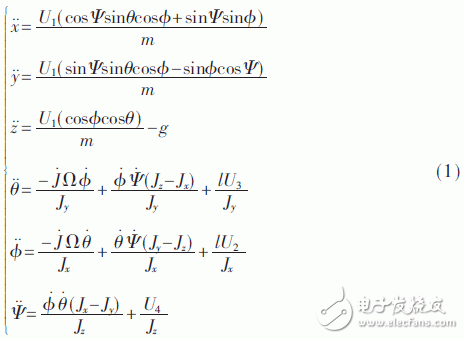
From the above equation, the quadrotor is an underactuated, nonlinear, and strongly coupled system. In this paper, the auto-disturbance rejection controller is used as the control system. At the same time, the modified EKF is used to modify the posture of the aircraft with noise. The control system model is shown in Figure 2.

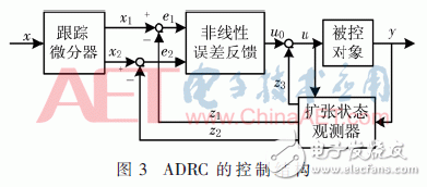
The auto-disturbance rejection control is to arrange the transition process by the tracking differentiator (TD) and use the extended observer (ESO) to track and estimate the coupling terms between the states. At the same time, the total disturbance of the system is estimated, and the nonlinear state is adopted according to the disturbance estimation value. Error feedback (NLSEF) compensates in real time. Its second-order structure is shown in Figure 3 [11].
The quadrotor attitude subsystem equation is as follows:
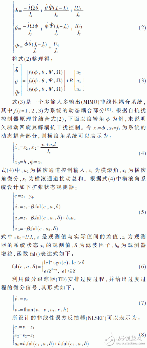
Where b1 and b2 are the controller gains.
The quality of the auto-disturbance rejection controller is related to the tuning of its internal module parameters. Therefore, it is necessary to set the parameters of each module of the auto-disturbance rejection controller.
2.3 Setting of auto-disturbance decoupling control parametersSince each module in the ADRC does not affect each other, the parameters of each module can be individually set and the overall adjustment can be made.
2.3.1 TD parameter tuningThe speed factor r in the tracking differentiator influences the speed of the tracking signal, and the effect thereof is shown in FIG. 4 . Where T=0.01, x=5 is the initial signal, and y is the tracking waveform, corresponding to the curves of the speed factors r=1, 5, and 14 respectively.
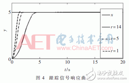
Figure 4 shows that the faster the speed factor r is, the faster the tracking speed is and the easier it is to cause overshoot and lose the significance of the differential tracker. The smaller the r tracking period, the worse the real-time performance of the system.
2.3.2 ESO parameter settingESO is the most important part of the ADRC. Generally, a1=0.5 and a2=0.25 are selected. σ is the width of the linear interval near the origin of the fal function. If σ is too large, some non-linear signals may not be accurately tracked, which greatly reduces the control effect of ADRC. If σ is too small, the phenomenon of signal jump appears near the origin and decreases. System stability. However, β1, β2, and β3 only affect the convergence rate of ESO and are not changed due to the change of control objects [12].
2.3.3 Setting NLSEF ParametersThe control gains b1 and b2 in NLSEF have a great influence on the control effect. The gain of control gain leads to system divergence and affects the security of the system. The smaller the control gain, the poorer the real-time performance of the system. Therefore, it should be dynamically adjusted according to different control systems.
3 Improved EKF Filtering Principles and AlgorithmsThis paper proposes an improved EKF algorithm. First, iteratively processes the observation matrix to improve the filtering accuracy. Then, the two-rotor EKF is used to predict and update the attitude data of the quadrotor, and the output state variables are weighted and integrated to output the optimal state estimation of the aircraft. The schematic diagram is shown in Figure 5.
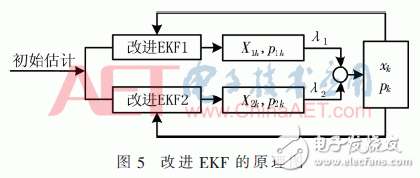
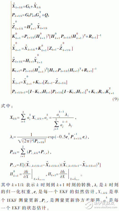
For a discrete stochastic system:  Where Wk, Vk are the process noise and the observed noise at the time of system k respectively and they are Gaussian white noises with a mean value of zero. The corresponding variances are Qk and Wk, respectively. The process of improving the EKF algorithm is as follows:
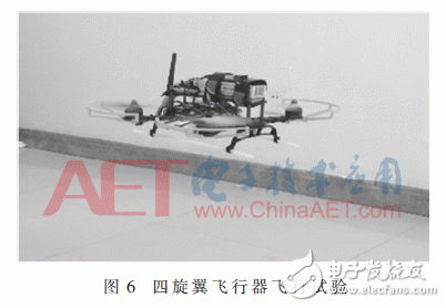
In the previous work, the simulation and experiment of the dual-loop PID and improved EKF flight disturbance control system have been completed. The actual flight effects of the aircraft under the control of the improved EKF ADRC are shown in Fig. 6.
In order to verify the effect of this method on the stability control of the quadrotor, the expected value of the given aircraft roll angle is θ=20°. The simulation results are shown in FIG. 7 .
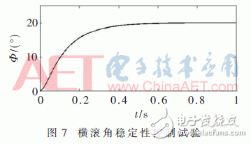
From Fig. 7, we can see that the pitch angle can reach the desired value in about 0.9 s, and there is no oscillation in the state adjustment process. It can be seen that this control method is very ideal for the stability control of the aircraft.
4.2 Improve EKF's auto-disturbance and cascade PID comparison experimentsThe initial value of a given roll angle is 0°, and the signal is a periodically changing square wave, where the square wave gain of the roll channel is φ=15°. The output curve of the system under the improved EKF auto-disturbance and cascade PID control is shown in Figure 8.
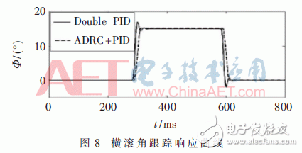
Figure 8 shows that both control methods have a good tracking effect on the roll angle, but the attitude angle response curve of the cascade PID controller will produce oscillations, but the improved EKF auto-disturbance control does not have this phenomenon. .
4.3 Height Control Contrast ExperimentThe initial altitude of a given quadrotor is 0 m and the expected altitude is 2 m. Its system output under the improved EKF auto disturbance rejection and cascade PID control is shown in Fig.9.
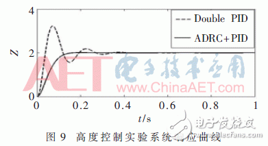
Figure 9 shows that under the expected value of 2 m, the overshoot of the cascade PID control is above 50% and the settling time is about 0.9 s, while the overshoot of the auto-disturbance rejection control curve of the improved EKF is below 5%. The time is about 0.5 s.
4.4 Improved EKF's ADRC, ADRC, and Cascade PID immunity comparison experimentsWhen the four rotors actually fly, the system is affected by sensor noise and external mutations. In order to simulate the noise of the sensor, Gaussian white noise is added to the feedback variable of the roll angle; in order to simulate the effect of external mutations, the time is 200 ms. The angular acceleration of the roll angle loop adds a square wave with a magnitude of 20 and a pulse width of 100 ms as the abrupt signal to detect the anti-jamming performance of the controller. The simulation results are shown in FIG. 10 .
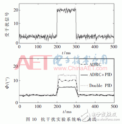
It can be seen from Fig. 10 that under the same conditions, the anti-jamming effect of the improved EKF ADRC is even more prominent.
4.5 Aircraft Actual Flight Roll Angle, Height CurveIn actual flight, given a sudden change in the amplitude of the roll angle of about 12, the amplitude of a given height is about 8. Using digital transmission of data to the computer, its curve on the host computer is shown in Figure 11.
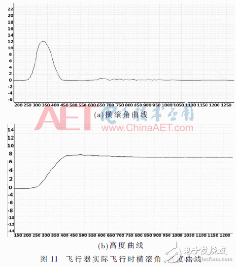
As can be seen from FIG. 11 , the four-rotor aircraft under the auto-disturbance rejection controller of the improved EKF can quickly achieve the recovery of the attitude angle and the height control, and achieve a stable flight of the aircraft.
5 ConclusionThe experimental results show that under the control of this method, the aircraft can quickly return to equilibrium from a roll angle of 50°, and the height control and anti-interference ability are more rapid and stable than the cascade PID control. In the following work, the obstacle avoidance and path planning of the quadrotor will be studied. The distance between the quadrotors and the obstacles will be measured using ultrasonics. The monocular vision will be used to locate the aircraft, and the four-rotor aircraft will eventually achieve autonomous flight. .
Nantong Boxin Electronic Technology Co., Ltd. , https://www.ntbosen.com