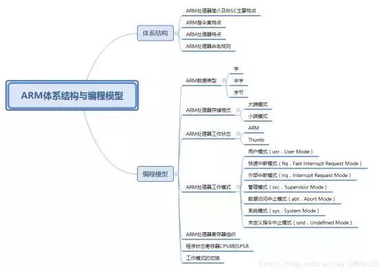
First ARM processor introduction and RISC features
ARM processor introduction
ARM (Advanced RISC Machines) is a 32-bit RISC (Reduced Instruction Set) processor architecture, and ARM processors are microprocessors under the ARM architecture. ARM processors are widely used in many embedded systems. ARM processor features fixed instruction length, high execution efficiency, and low cost.
Main features of RISC design
1, the instruction set - RISC reduces the type of instruction set, usually one instruction per cycle, using a fixed-length instruction format, the compiler or programmer through a few instructions to complete a complex operation. The instruction length of the CISC instruction set is usually not fixed.
2, the pipeline - RISC uses a single-cycle instruction, and the instruction length is fixed, which is convenient for pipeline operation.
3. Registers - RISC's processors have more general-purpose registers and more register operations. For example, an ARM processor has 37 registers.
4, Load / Store structure - use load / store instructions to read and write data from memory in bulk, improve data transmission efficiency.
5. The addressing mode is simplified, the instruction length is fixed, and the instruction format and addressing mode are reduced.
The second ARM instruction set features
The ARM processor is based on RISC, but not a pure RISC architecture. In order to make the ARM processor better meet the needs of the embedded system, the ARM instruction set and the pure RISC instruction set have the following differences:
1. The number of specific instruction cycles is variable. For example, the load cycle of a multi-register load or store Load/Store instruction is undefined, depending on the number of related registers. If you access consecutive memory addresses, you can improve performance because continuous memory access is faster than random access. According to this feature, since there are usually multiple registers and memory for data exchange at the beginning and end of the function, the number of instructions for the corresponding operation is reduced, which increases the density of the code.
2. The embedded barrel shifter produces more complex instructions. The barrel shift register is a hardware component that processes the data in this register before a register is used by an instruction. The barrel shifter extends the functionality of many instructions to improve core performance and increase code density.
3, Thumb16 bit instruction set. The ARM processor has two working states, one is the ARM state and the other is the Thumb state. The instruction length is 32 bits in the ARM state and 16 bits in the Thumb state. This feature allows the ARM to perform both 16-bit instructions and 32-bit instructions, enhancing the functionality of the ARM core.
4. Conditional execution. The instruction will only be executed when a particular condition is met. This feature can reduce the number of branch instructions, thereby improving performance and increasing code density.
5. Enhance the instructions. Some powerful digital signal processor (DSP) instructions have been added to standard ARM instructions to support fast 16*16 multiply operations and saturation operations. These enhanced instructions from ARM allow the ARM processor to be implemented without the need for a DSP.
Third ARM processor features
1, ARM instructions are 32-bit fixed length
2, a large number of registers (37 registers)
3, the ordinary Load / Store instruction
4, multiple register Load / Store instruction
5. Conditional execution of instructions
6. A single instruction in a single clock cycle completes the data shift operation and the ALU operation.
7. Extend the capabilities of ARM processors through variants and coprocessors
8, extended 16-bit Thumb instructions to improve code density
Fourth ARM processor naming rules
ARM programming model
1. Word: In the ARM architecture, the length of the word is 32 bits.
2, half word (Half-Word): In the ARM architecture, the length of the halfword is 16 bits.
3. Byte: In the ARM architecture, the length of the byte is 8 bits.
ARM processor storage format
The ARM architecture treats memory as a linear combination of bytes starting at address zero. As a 32-bit microprocessor, the ARM architecture supports a maximum address space of 4GB.
The ARM architecture can store word data in two ways, big endian mode and little endian mode.
Big endian mode (high ground): The high byte of the word is stored in the low address byte location and the low byte of the word is stored in the high address byte location.
Little endian mode (high, low, low): The high byte of the word is stored in the high address byte unit and the low byte of the word is stored in the low address byte unit.
ARM processor working status
From a programming point of view, ARM microprocessors generally have two working states, ARM and Thumb, and can switch between the two states.
1. ARM state: At this time, the processor executes a 32-bit word-aligned ARM instruction, and most of the work is in this state.
2. Thumb state: At this point the processor executes a 16-bit halfword aligned Thumb instruction.
ARM processor working mode
1. User mode (usr, User Mode): The normal program execution state of the ARM processor.
2. Fast Interrupt Request Mode (fiq): used for high-speed data transmission or channel processing. Enter this mode when a fast interrupt is triggered.
3. External interrupt mode (irq, Interrupt Request Mode): Used for general interrupt processing. Enter this mode when an external interrupt is triggered.
4. Management mode (svc, Supervisor Mode): The protection mode used by the operating system. Entered when the system is reset or the software interrupt instruction SWI is executed.
5, data access abort mode (abt, Abort Mode): When the data or instruction prefetch abort enter this mode, can be used for virtual storage and storage protection.
6, system mode (sys, System Mode): run a privileged operating system task.
7. Undefined Instruction Abort Mode (und, Undefined Mode): Enter this mode when an undefined instruction is executed, which can be used to support software emulation of hardware coprocessor.
In addition to the user mode, the other six modes are privileged mode. Except for user mode and system mode, the other five modes are abnormal modes.
In privileged mode, the program can access all system resources. The difference between non-privileged mode and privileged mode is that some operations can only be allowed in privileged mode, such as direct mode change and interrupt enable. Moreover, in order to ensure data security, the MMU generally divides the address space, and only the privileged mode can access all the address spaces. User mode, if you need to access the hardware, must switch to privileged mode to allow access to the hardware.
ARM processor register organization
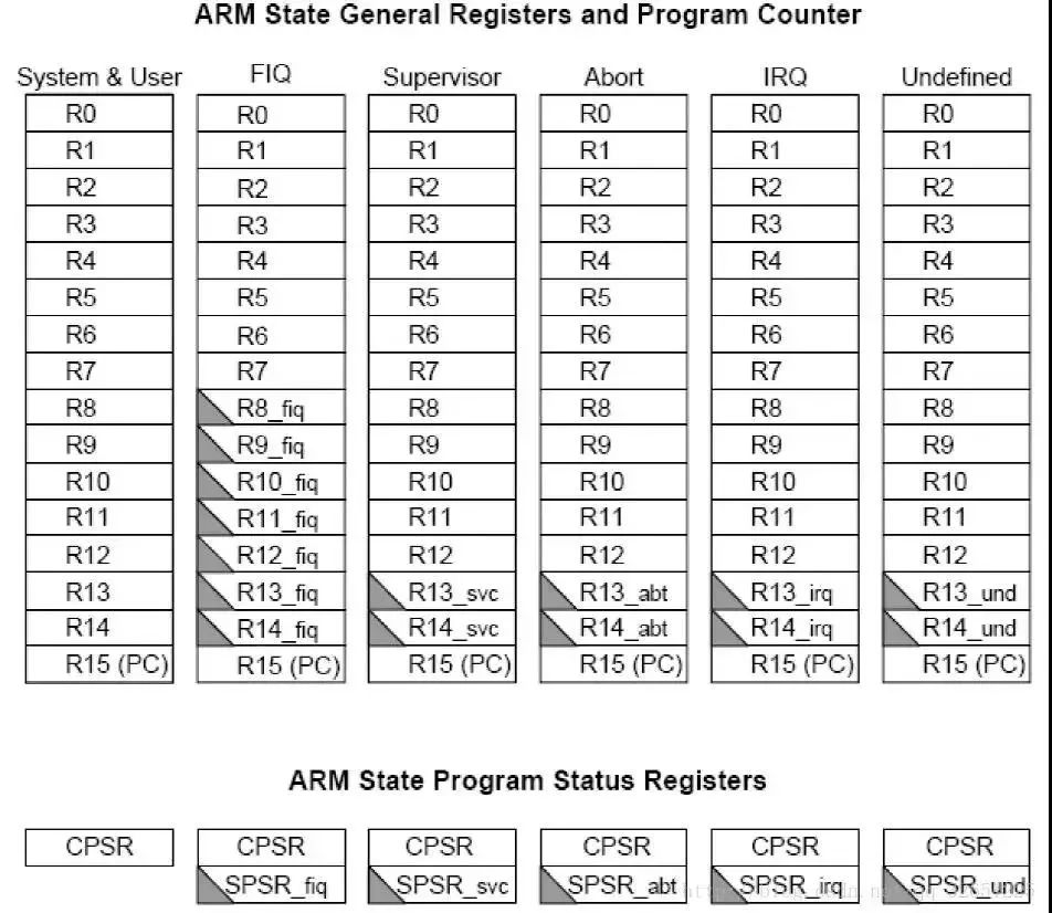
ARM has 37 32-bit registers, of which 31 are general-purpose registers and 6 are status registers, including R0-R15, R8_fiq-R14_fiq, R13_svc, R14_svc, R13_abt, R14_abt, R13_irq, R14_irq, R13_und, R14_und, CPSR, SPSR_fiq, SPSR_svc, SPSR_abt, SPSR_irq, SPSR_und. As shown.

General-purpose registers include R0-R15, which can be divided into three categories:
1. Ungrouped registers R0-R7
In all modes of operation, ungrouped registers point to the same physical register and they are not used by the system for special purposes. Therefore, when an exception mode conversion is performed during interrupt or exception processing, the same physical registers are used in different processor operating modes, which may cause data corruption in the registers.
2. Group register R8-R14
For grouped registers, the physical registers they access each time are related to the current processor operating mode. Specifically as shown above.
R13 is often used to store stack pointers. Users can also use other registers to store stack pointers. However, under the Thumb instruction set, some instructions force R13 to store stack pointers.
R14 is called a link register (LR, Link Register). When a subroutine is executed, R14 can get a backup of R15 (PC). After executing the subroutine, copy the value of R14 back to the PC, that is, use R14 to save the return address.
3. Program Counter PC (R15)
Register R15 is used as the program counter (PC). In the ARM state, bits [1:0] are 0, bits [31:2] are used to save the PC; in Thumb state, bit [0] is 0, bit [31] :1] is used to save the PC.
Since the ARM architecture uses multi-stage pipeline technology, for the ARM instruction set, the PC always points to the address of the next two instructions of the current instruction, that is, the value of the PC is the address value of the current instruction plus 8 bytes.
Program Status Registers CPSR and SPSR
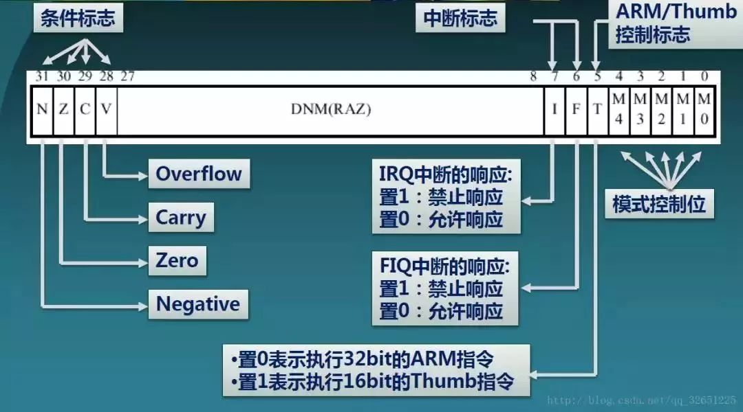
CPSR (Current Program Status Register), CPSR can be accessed in any operating mode, including condition flag bits, interrupt disable bits, current processor mode flag bits, and other related control and status bits.
In each mode of operation, there is a dedicated physical status register called SPSR (Saved Program Status Register). When an exception occurs, the SPSR is used to save the current CPSR value. The CPSR can be restored by the SPSR.
Since the user mode and the system mode are not in the abnormal mode, there is no SPSR in these two states, so accessing the SPSR in these two states, the result is unknown.
The structure of the CPSR to save data:

1. N (Negative): When the operation is performed with the signed number represented by two complements, N=1 indicates that the result is negative, and N=0 indicates that the result is positive or zero.
2. Z (Zero): Z = 1 indicates that the operation result is 0, and Z = 0 indicates that the operation result is non-zero.
3.C (Carry): There are 4 ways to set the value of C:
(1) Addition instruction (including comparison instruction CMP)
(2) When the operation produces a carry (unsigned number overflow), C=1, otherwise C=0
(3) Subtraction (including comparison instruction CMP)
(4) When the operation produces a borrow (unsigned overflow), C=0, otherwise C=1
For a non-add/subtract operation instruction that includes a shift operation, C is the last bit of the shifted value. For other non-addition/subtraction instructions, the value of C is usually unchanged.
4. V (Overflow): There are 2 ways to set the value of V:
(1) For the add/subtract operation instruction, when the operand and the operation result are the signed number represented by the binary complement, V=1 indicates that the sign bit overflows.
(2) For other non-addition and subtraction instructions, the value of V is usually unchanged.
5. I (Interrupt Request): I=1 means that the response is prohibited, and I=0 means that the response is allowed.
6. F (Fast Interrupt Request): F=1 means prohibiting response fiq, F=0 means allowing response
7. T(Thumb): T=0 indicates the current status bit ARM status, T=1 indicates the Thumb status
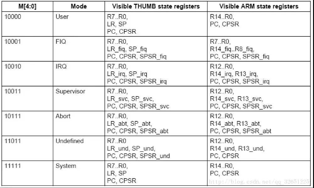
8. M4-M0: indicates the working mode of the current processor, as shown in the figure:

Work mode switching
(1) Execute a soft interrupt (SWI) or a reset command (Reset). If the SWI instruction is executed in user mode, the CPU enters the Supervisor mode. Of course, executing SWI in other modes will also enter this mode, but the general operating system will not do this, because other modes are privileged mode except that user mode is non-privileged mode. Execution of SWI instructions is generally to access system resources, while access to all system resources in privileged mode. SWI instructions are generally used to provide an API interface to the operating system.
(2) An external interrupt has occurred. If an external interrupt occurs, the CPU enters IRQ or FIQ mode.
(3) An exception is generated during CPU execution. The most typical exception is due to memory access exceptions caused by MMU protection, when the CPU switches to Abort mode. If it is an invalid instruction, it will enter the Undefined mode.
(4) There is a mode that the CPU cannot automatically enter. This mode is the System mode. To enter the System mode, it must be implemented by the programmer. To enter the System mode, simply change the mode bit of the CPSR to the mode bit corresponding to the System mode. Entering the System mode is generally to take advantage of the same features of the registers in the System mode and the user mode. Therefore, in general, after the operating system enters the Supervisor mode through the SWI, it enters the System mode after doing some operations.
(5) In any privileged mode, you can enter other modes by modifying the MODE field of the CPSR. However, it should be noted that since the modified CPSR is the shadow CPSR in this mode, that is, the SPSR, it is not the actual CPSR. Therefore, the general practice is to modify the shadow CPSR, and then execute a MOVS instruction to resume execution of a breakpoint and switch. Go to the new mode.
Ungrouped
- [Worldwide Compatibility]With a worldwide 100-240V AC input, it's a truly global charger and perfect for international traveling. Compatible with iOS, Android, & Windows smart phones as well as tablets, speakers, cameras, and other 5V USB devices
-
With 9 years experience in the filed, Shenzhen WAWEIS Technology Co., Ltd is one of the best power supply device manufacturer in China. Our world-class production plant passed ISO9001:2008 & ISO14001:2004 certifications and is equipped with the state-of-art technology and machines. The main products we make are power adapters, which can be used in laptop, LCD display, LED lights, CCTV camera(12v series), Speaker(24v series), Balance car(42v series). All our products comply with European environmental standard as well as CCC,RoHS ,CE , FCC.
Ungrouped,High Quality Ungrouped,Ungrouped Details, CN
Shenzhen Waweis Technology Co., Ltd. , https://www.waweis.com