The drone has the characteristics of small size, light weight, flexibility, low cost, etc. It can be used for photographing of ground reconnaissance, and can also be widely used in military reconnaissance, geological exploration, and survey and prediction of dangerous areas such as fires. It is very important to build a network video system on the human machine. Based on PC104-based drones, this paper constructs a network video system. The acquisition, compression, decompression and transmission of drone video data are the key technologies in the UAV network video system. Several key issues are studied.
1 system structure and working principle
The lower position machine of the system is mainly composed of PC104 industrial computer of Shenzhen Sunda Company, MP camera (USB interface) of Logitech Express space version, USB router of linksysWRT54GC-CN and peripheral circuits. It adopts embedded Linux 2.4.26 operating system and is mainly responsible for Video data is collected, compressed and sent to the host computer. The host computer is a PC computer containing a wireless network card. It is mainly responsible for receiving, decompressing and displaying video data. The upper and lower computers transmit data through UDP/IP network protocol. The socket network programming can realize network interconnection and data transmission and reception.
PC104 industrial computer uses embedded dedicated CPU PIII533 ~ 933 MHz, onboard DDR memory up to 128
MB, provides 2 RS 232 serial interfaces, 2 USB ports, 1 parallel port, floppy disk drive interface, IDE hard disk drive, 10/100 Base-TX Ethernet interface, CRT/LCD display interface and SSD socket, supports DiskOnChip 8 to 288 MB. The operation and use of the PC104 industrial computer is the same as that of the PC. After the system hardware is installed, the BIOS can be turned on for BIOS setting. The input voltage must be +5 V, and the fluctuation range should not exceed 5%.
2 software implementation of video data acquisition
Video4Linux (V4L) is the kernel driver for video devices under embedded Linux. It provides a series of interface functions for video devices under Linux. In the stage of compiling and configuring the kernel, you must add support for V4L modules and USB camera driver modules. For the USB interface camera, the driver needs to provide the basic I/O operation functions open, read, write, close, the implementation of the interrupt, the memory mapping function and the implementation of the control interface function ioctl for the I/O channel. Etc. and define them in the struct file operaTIons. Thus, when the application makes a system call operation such as open to the device file, the Linux kernel will access the function provided by the driver through the fileoperaTIons structure. Drive the USB camera on the system platform, firstly compile the USB controller driver module into the kernel statically, so that the platform supports the USB interface, and then use the insmode to dynamically load its driver module when you need to use the camera to capture, so that the camera can be normal. Already working.
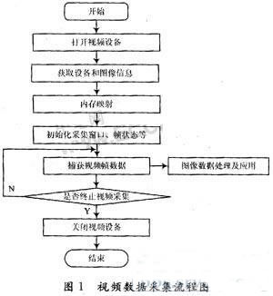
After the USB camera is driven, the video data acquisition can be realized by programming several video acquisition related data structures supported by Video4Linux. Figure 1 shows the flow of video data collection under embedded Linux:
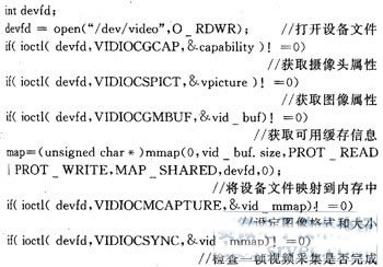
Use the ioctl (devfd, VIDIOCSYNC, & vid_mmap) function to determine whether an image has been intercepted. A successful return indicates that the interception is complete, and then the image data can be saved as a file. In order to obtain a continuous frame video image, the number of times the camera frame buffer frame data is collected and looped may be determined by using the vid_buf.frames value on a single frame basis. In the loop statement, each frame is also intercepted using the VIDIOCMCAPTURE ioctl and VIDIOCSYNC ioct1 functions, but to assign an address to each captured image, use the statement buf=map+vid_buf.off-sets[frame], and save it as a file. form.
3 video data compression principle
The lower computer of the UAV system requires real-time transmission of video data to the host computer. Since the amount of video data is large and the network bandwidth is very valuable, it is very important to select a file format with high compression ratio for video data. JPEG is the English abbreviation of Joint Picture Expert Group. It is a compression coding standard for static images jointly developed by the International Organization for Standardization (ISO) and CCITT. Compared to other common file formats of the same image quality (such as GIF, TIFF, PCX), JPEG is currently the highest compression ratio in still images, but the image quality is similar. It is because of the high compression ratio of JPEG that he is widely used in multimedia and network programming.
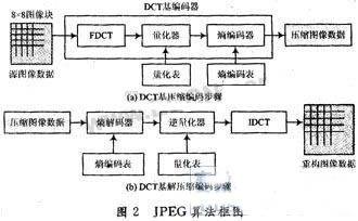
The JPEG-expert group developed two basic compression algorithms, one is a lossy compression algorithm based on Discrete Cosine Transform (DCT), and the other is a lossless compression algorithm based on prediction technology. . When using the lossy compression algorithm, in the case of a compression ratio of 25:1, the image obtained by compression and reduction is compared with the original image, and it is difficult for non-image experts to find out the difference between them, and thus has been widely used. JPEG compression is lossy compression. It takes advantage of the characteristics of the human view system and uses a combination of quantization and lossless compression coding to remove the redundant information of the view and the redundant information of the data itself. The block diagram of the JPEG algorithm is shown in Figure 2.
Compression coding is roughly divided into three steps:
(1) Data redundancy is removed by DCT. DCT is an important step in image compression. It transforms an image from a spatial domain to a frequency domain by orthogonal transform. For N&TImes; N-dimensional data, N×N data is still obtained after transformation. Although the DCT transform itself does not compress the image, the transform eliminates the redundancy between the N×N-dimensional data. The DCT transform is the basis for quantization and coding in the compression process.
(2) Quantize the DCT coefficients using a quantization table. The quantization table is a matrix of quantized coefficients, which can reduce the precision of integers and reduce the number of bits required for integer storage. The quantization process removes some of the high frequency components and loses detail on the high frequency components. Since the human visual system is far less sensitive to high spatial frequencies, the quantized image has little loss from the visual effect. Since the low spatial frequency contains a large amount of image information, after the quantization process, a large number of consecutive zeros appear in the high spatial frequency segment, which is advantageous for reducing the amount of data by encoding later.
(3) Encode the quantized DCT coefficients to minimize their entropy. After the DCT and quantization of the remote sensing image data, a large number of consecutive zeros appear in the high frequency segment, and the Huffman variable word length coding is used to minimize the redundancy.
The process of decoding or decompression is exactly the opposite of the compression encoding process. According to the above JPEG data compression and decompression principle, the image compression and decompression program is developed and implemented in the C compiler and the integrated development environment (Code Composer Studio, CCS), which can be applied to the processing of drone video data. The interface of the video data compression handler is as follows:

4 network transmission protocol and socket programming
According to the OSI network standard definition, the network consists of a physical layer, a data link layer, a network layer, a transport layer, a session layer, a presentation layer, and an application layer. In practical applications, the network structure may adopt a link layer, a network layer, a transport layer, and an application layer 4-layer model.
In the TCP/IP protocol suite, the IP protocol is a network layer protocol. The TCP protocol is a connection-oriented protocol that provides reliable, full-duplex network communication services with acknowledgment, data flow control, multiplexing, and data synchronization for high-quality data transmission. One of the most widely used network transport protocols. However, due to the complex implementation of the TCP protocol, the network overhead, and the acknowledgment and timeout retransmission mechanism provided by the TCP protocol bring great delay to the data transmission. Therefore, the TCP protocol is not suitable for transmitting real-time video data and bursty large amounts of data.
The UDP protocol is a connectionless protocol, the message exchange is simple, and there is no multiple acknowledgment mechanism, thereby reducing the huge overhead required to establish a connection and remove the connection. Each packet carries a complete destination address and is transmitted independently in each packet system. He does not guarantee the sequence of packets, and does not perform packet error recovery and retransmission. Therefore, transmission reliability and quality of service cannot be guaranteed. However, compared with the TCP protocol, the UDP protocol reduces operations such as acknowledgment and synchronization, which saves a lot of network overhead. He is able to provide high-transmission efficiency datagram services, enabling real-time data transmission and widespread use in real-time data transmission. In order to ensure the real-time performance of drone video data transmission, IP protocol and UDP protocol are adopted as the communication protocol of the system.
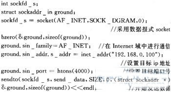
The software implementation of the network transmission part of the system adopts the socket (programming) programming technology. The system calls the socket() function to return an integer socket descriptor. The video data transmission is realized by the socket function. Commonly used socket types correspond to two types of transport protocols: streaming sockets and datagram sockets. The former uses the TCP protocol, the latter uses the UDP protocol, and the system uses a datagram socket. The following is the main implementation of the socket programming of the lower computer:
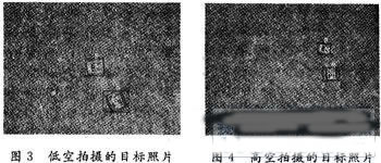
The wireless network card of the upper computer is responsible for receiving the video data of the lower computer, and decompressing and displaying the video data according to the decompression principle of the JPEG image. Fig. 3 and Fig. 4 can see the effect of collecting video data from the lower computer and sending it to the upper computer through processing and then displaying it.
5 Conclusion
This paper mainly introduces a video system construction method and process based on PC104 drone. Taking PC104 industrial computer as the main hardware platform, it completes the detailed introduction and software design of the process of capturing, compressing and transmitting video data of camera. The network UDP/IP network transmission protocol and socket programming transmit video data, which guarantees a certain degree of real-time performance, and can meet the application of the UAV geological exploration, fire reconnaissance and other fields.
In conclusion, reading is a hobby that brings me immense pleasure and enriches my life in numerous ways. It stimulates my mind, enhances my creativity, and broadens my horizons. I am grateful for the world of books and the endless possibilities they offer.

In conclusion, reading is
2222Bossgoo(China)Tecgnology.
(Bossgoo(China)Tecgnology) , https://www.tlqcjs.com