Cree XLamp® High Power Devices Latest Application Guidelines and Points to Watch Updates
——XLamp® LED Pulse Overcurrent Drive: Related Information and Precautions
This article elaborates on three types of safety problems that are often encountered by customers in the pulse mode of operation of LEDs exceeding the maximum rated current value, especially for emergency vehicle applications, dedicated stroboscopic illumination, and even pulse modulation for general illumination dimming applications. The effect on LED operation and performance under overcurrent conditions.
Electrical overload (EOS) is often associated with catastrophic failures such as electrostatic discharge (ESD), inrush current, or other types of transient surges. The designer of the LED driver should ensure that all necessary precautions are taken to protect the LED from EOS damage. The second type of overcurrent condition is often associated with LED applications operating in flash mode, such as emergency vehicle lights, strobe lights, or signal lights, often using high frequency pulses (ie, greater than 120 Hz) to control the brightness of the LEDs in dimming applications. Finally, the ripple current is a periodic repeating peak-to-peak variation in the DC waveform due to insufficient filtering of the AC or switching power supply. These conditions do not affect the long-term lumen maintenance or reliability of the LEDs within specifications. However, in the case of "overcurrent" (that is, beyond the data sheet specifications), they shorten the life of the LED.
One, single pulse over current
Single-pulse overcurrents are often caused by inadvertent use of excess electrical energy to one or more LEDs, often resulting in catastrophic failure of the device. Cree XLamp® LEDs can withstand transient currents several times higher than the maximum rated current. However, how much current amplitude a particular LED device can withstand is also related to the duration and frequency of the transient current. If a certain threshold is exceeded, a single pulse will cause an immediate catastrophic failure of the LED. In this case, there are usually two failure modes: short circuit or open circuit.
The main influencing factor that limits the ability of an LED to withstand EOS is the current carrying capability of the LED chip and internal interconnect components (ie, bond wires).
A local increase in current density, called current concentration, is an uneven distribution of current density in a conductor or semiconductor, especially for electrode contact points and pn junctions of LEDs. Current concentration limits LED efficiency and is particularly prone to materials with low carrier mobility, such as indium gallium nitride (InGaN). The current set gathering causes local overheating and forms a hot spot, which causes heat dissipation in severe cases, and may also exacerbate electromigration effects and void formation, resulting in uneven local distribution of current density. The increase in resistance around the void is a self-feedback loop that causes a further increase in local temperature, which accelerates the formation of voids and may eventually lead to open loop failure.
Conversely, the current density is locally reduced with a certain current density gradient, which may result in the deposition of ions that migrate from the "aggregated" region of the current. In a similar self-propagating cycle, this may result in a further decrease in current density, as well as further deposition of the migrating ions, and even the formation of small protrusions, causing a short circuit.
Figure 1 below depicts two scenarios of metal migration. The image on the left shows a device with a repetitive transient current below the maximum threshold. The device shown on the right shows a voltage that is approximately 20 times the normal forward voltage, resulting in severe transient failure.
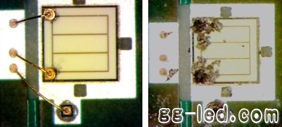
Figure 1: Metal migration: an example of two cases
Second, repeated pulses
The second type of overcurrent condition, high current repetitive pulse, may cause early catastrophic failure of the LED, but it is not inevitable. High current repetitive pulses can result in a shortened LED life expectancy, which can be reduced by tens of thousands or hundreds of thousands of hours compared to the usual life expectancy. When the device experiences repeated transient currents that are several percentage points above the data sheet limits, although below the single-pulse failure threshold, failures will still occur. The failure mechanism is most likely due to the migration of too many metal ions from their original lattice positions resulting in electron migration.
Cree tested the pulse currents in different current ranges for four different XLamp® LEDs. The data shows that at a certain current level, the light output is hardly increased and the efficiency is reduced. Therefore, Cree does not recommend that customers apply such extreme currents to LEDs. The following figure shows the current values ​​and light when the white light XP-C, XP-E, XP-G, and MX-6 LED devices operate at 1000 Hz and three different duty cycles (5%, 20%, and 50%). The relationship between the effects, this result information is for illustrative purposes only, not for specifications. The vertical dashed line represents the maximum rated continuous current for each XLamp® LED product type.
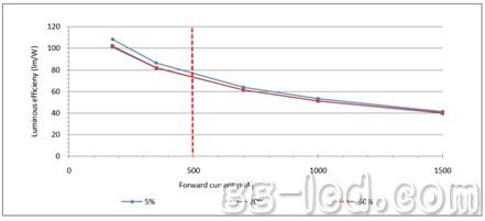
Figure 2: Relationship between XP-C efficacy and input current [Q3 bin]
(vertical dashed line is the maximum rated continuous current, 500 mA) 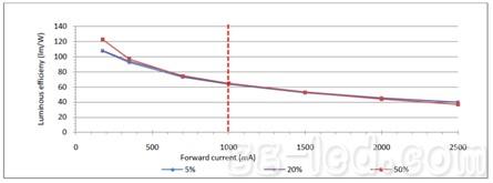
Figure 3: Relationship between XP-E efficacy and input current [R4 bin]
(vertical dashed line is the maximum rated continuous current, 1000 mA) 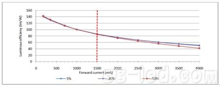
Figure 4: Relationship between XP-G efficacy and input current [R5 bin]
(vertical dashed line is the maximum rated continuous current, 1500 mA) 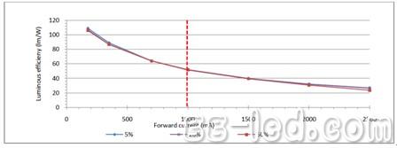
Figure 5: Relationship between MX-6 efficacy and input current [Q3 bin]
(vertical dashed line is the maximum rated continuous current, 1000 mA)
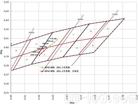
Figure 6: XP-E Warm White, Drive Frequency 1 KHz, 20% Duty Cycle, Under Current and Over Current Settings 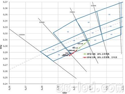
Figure 7: XP-E cool white, drive frequency 1 KHz, 20% duty cycle, undercurrent and overcurrent settings

Elevator Advertising Projector
Elevator projector,projector Elevator,elevator projection,elevator projector advertising,Smart elevator projector,elevator advertising projector
Guangdong Elieken Electronic Technology Co.,Ltd. , https://www.elieken.com