For satellite-based space-based information systems, the use of terrestrial high-performance IP switches still has major problems, making its use in space-based information systems limited.
(1) Power consumption: On-board devices have strict control over power consumption. Ground-based high-performance backbone IP switches typically consume hundreds of watts to several kilowatts, which is unbearable for on-board equipment.
(2) System reliability: On-board equipment requires extremely high system reliability, and redundant backup problems need to be considered at different levels.
(3) System weight and volume: The weight of the star load is an important indicator of the satellite system. The spaceborne high-performance switch must be greatly reduced in volume and weight compared with the ground equipment.
(4) System hardware structure optimization: The hardware complexity and integration of the IP switch system are very high, but due to the influence of space temperature environment, space particle flow, etc., there are great constraints on component selection, and SDRAM is widely used in ground equipment. Devices such as DDR and high-performance CPUs cannot be directly used. This requires that the complexity of the system hardware structure and algorithm must be reduced, so that it can be realized on the basis of available aerospace-class components (such as low-speed SRAM, processor and memory). Exchange capacity.
(5) System software structure optimization: The software complexity of the IP router system is very high. Because the high-performance network processor cannot be directly used in the space-based information system, some functions and algorithms that are traditionally implemented by software should adopt the hardware curing method. to fulfill. This requires simplifying the complex IP stack.
Based on the above analysis, the use of terrestrial high-performance IP switches in space-based information systems has been greatly limited. Since the on-board memory capacity cannot be as wide as the ground, the queue length is limited, and the round-trip propagation delay of the satellite air interface is larger than the ground. In order to better design the flow control, a low complexity is required in the on-board switch structure. An effective queue manager reduces the requirement for buffer capacity, guarantees low latency, reduces packet loss rate, meets user QoS requirements, and improves throughput.
1 basic concept
In the on-board switch, in order to implement fast forwarding of IP data packets, a fixed-length cell-based system is generally adopted, and IP data packets are divided into a plurality of fixed-length packets (hereinafter collectively referred to as cells) before entering the switching structure. The cache structure of the switch structure mainly includes an input cache, an output cache, and a shared cache. For an N×N switch fabric, the access speed of the memory in the output buffer is (N+1) times the line rate; the shared buffer mode is 2×N times the line rate; and for the input buffer mode, the access speed of the memory is Double the line rate, regardless of the number of ports on the switch. In order to increase the capacity of the switch and support higher line rates, it is necessary to study the input buffer in the onboard switch.
For the head-line blocking (HOL) problem in the input buffer, the virtual output queuing (VOQ) technique can improve the problem and achieve 100% throughput. For VOQ to achieve high performance, the key issue is to design an efficient and fair scheduling algorithm that matches the input and idle output ports, which is the matching problem of the bipartite graph.
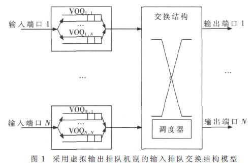
The input queued exchange structure model using the virtual output queuing mechanism is shown in Figure 1. In the buffer area of ​​each input port, N (N is the number of switch ports) FIFO queues are set, and each FIFO queue corresponds to one output port. That is to say, the packet whose input port is i and whose output port is j is buffered into the virtual output queue VOQi,j, and the packets in the matched VOQi,j are scheduled to be dispatched under the control of the scheduler.

2 queue manager structure
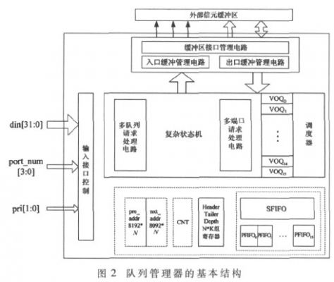
The queue manager is composed of an input control interface circuit, a multi-queue request processing circuit, a multi-port request processing circuit, a buffer interface control circuit, a scheduler and the like. The basic structure of the queue manager is shown in Figure 2.

The input control interface circuit cuts the received IP data packet into a number of 64 B-length cells and performs the necessary identification for IP packet reassembly. Each cell contains a header, and the header structure includes a destination output port, a priority, and an extendable identifier. The multi-queue request processing circuit divides the cell stream into a plurality of VOQ queues according to the output port and priority of the cell, and the multi-port request processing circuit reads the cell from the cell buffer under the control of the scheduler.
Let the on-board switch have K output ports, and the cells have N priority levels. The address space of the cell buffer (SRAM) is divided into K private areas and one shared area. The private area k (1 ≤ k ≤ K) can only be occupied by cells destined for the kth output port, and the shared area can be occupied by cells destined for any output port. Set K private FIFOs (PFIFO1, PFIFO2, ..., PFIFOK) and 1 shared FIFO (SFIFO). All available addresses of the private area k (1 ≤ k ≤ K) are recorded in (PFIFOK), and all available addresses of the shared area are recorded in the SFIFO. 

Laptops,windows,win11,win10
Jingjiang Gisen Technology Co.,Ltd , https://www.gisentech.com