This paper studies a self-tracking mobile target vehicle control system that can autonomously identify the path. The system uses ordinary rubber strips or paint ribbons as guide lines, and uses the camera sensor to dynamically extract the position of the guide line to determine the target. The running attitude of the car, and then control the moving direction of the target car, realize the function of autonomous recognition of the path.
1 Working principle of the system In practical applications, the target vehicle is equipped with thick protective steel plates and bulletproof rubber, and the inertia is large when moving and parking is difficult to control. Moreover, the shooting vehicle requires movement speed and curve curvature of the target vehicle Not high, so the self-tracking moving target vehicle adopts a three-wheel structure driving method. The front two wheels act as independent main drive wheels, and the rear wheels are universal wheels. In addition to being responsible for forward and backward, the first two wheels can realize the curve walking and in-situ rotation of the target vehicle when the rotation speed is different.

The entire control system can be divided into three parts: detection system, control decision system and power system. The detection system is equivalent to the "eye" of the target vehicle, collecting the path information of the target vehicle's movement; the control decision system is equivalent to the "brain" of the target vehicle, ensuring the system's stable, coordinated, and orderly work; the power system is used to complete the target vehicle's Various sports gestures. The working information flow of the system is shown in Figure 1. The detection system collects the path information of the target vehicle's movement in real time. After analyzing and processing the control decision system, the control power system makes corresponding adjustments to achieve precise positioning and action control of the target vehicle's position. .
2 System hardware circuit and software design
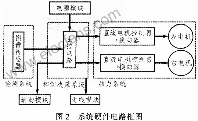
2. 1 hardware circuit The system hardware platform is mainly composed of image acquisition module, host control circuit and motor drive circuit, as shown in Figure 2.

2.1.1 The host control circuit is based on ATMegal28 integrated with 64 Kh Flash memory and rich hardware interface circuit, not only can directly drive the relay, but also the phase frequency correction PWM mode of the timer is based on double ramp operation can produce high precision, The accurate PWM waveform of both phase and frequency is suitable for the speed control of the motor, so the minimum system of ATMegal28 is adopted as the host control circuit of the system.
2.1.2 Image acquisition module The system uses the OV7620 camera module to collect path information. The OV7620 image sensor not only can directly output the horizontal and vertical synchronization interrupt signal, but also has automatic gain and automatic white balance control, and can perform various adjustment functions such as brightness, contrast, and saturation, which not only saves the complicated video decoding process. Moreover, the target vehicle can be adapted to different application environments. In fact, the target car does not need a high-resolution image. On the contrary, a lower-resolution image not only helps to reduce the space used for storage, but also speeds up the image processing speed of the microcontroller. Combined with the field of view of the camera, the system reduces the image acquisition resolution from the original 492x664 to 25x47, ensuring that the system can quickly and effectively collect road force information.
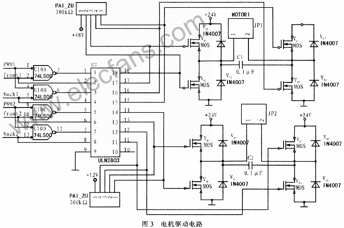
2.1.3 Although the bipolar reversible PWM system of the motor drive circuit runs smoothly at low speed, the current fluctuation is large and the power loss is large. In particular, a dead zone must be added to avoid the danger of the switch tube passing through, which limits the switching frequency. Improve, so the system uses unipolar reversible PWM to drive the motor, which avoids the straight-through of the switch tube and improves the reliability of the system. Although there will be a current interruption at light load, it can be overcome by increasing the switching frequency or improving the circuit design. It has the advantages of strong driving ability, simple control, fast speed, high reliability and low cost. The drive controller circuit is shown in Figure 3.

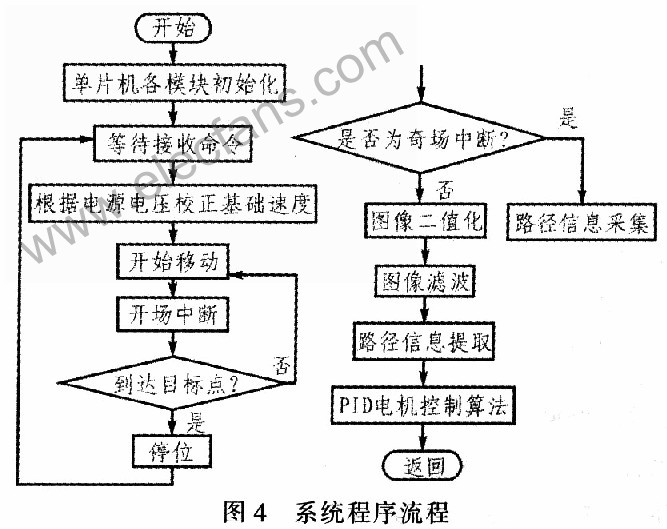
2.2 System software design When the system receives the correct movement command, the target vehicle enters the tracking mode. During the movement, it judges whether it reaches the target position according to the passing auxiliary parking bar, and finally stops at the target point. During the movement, the target vehicle must know where it is at any time and decide how to move next.
In order to be able to detect the path information in real time and reliably, and ensure that the target vehicle responds in time, the entire tracking control process is completed in the interruption. The software flow of the system is shown in Figure 4.

In order to obtain a stable control effect, the motor control uses digital incremental PID control algorithm. The target vehicle position deviation obtained after image processing is adjusted by proportional, integral, and differential operations, and the rotation speeds of the left and right motors are adjusted according to the result, so that the target vehicle responds quickly and accurately to the current path. The incremental PID control algorithm is shown in equation (1), where Kp, Ki, and Kd are the proportional coefficient, integral coefficient, and differential coefficient of the controller, respectively. ![]()
The offset error increment ΔU of the target vehicle is only related to the current deviation ek, the last deviation ek-1, and the last deviation ek-2. Under normal circumstances, it will fluctuate within a relatively small range and finally reach smooth control. Considering that the controlled variable may overflow or be less than zero, the upper limit Ui_max and the lower limit Ui_min are set for the output increment.
Since the target vehicle does not have a fixed mathematical model, the engineering tuning method is used to determine the parameters of the PID controller. The method is to first set the PID parameters on certain values ​​based on experience, and then observe the system response, and then adjust the corresponding parameter scale according to the specific effect until the appropriate control parameters are found.
3 Conclusion This paper mainly expounds the design scheme and realization method of the three major functional modules of the self-tracking mobile target vehicle detection system, control decision system and power system. Due to the convenient path laying, low cost, strong real-time performance, and flexible maneuverability, the self-tracking mobile target vehicle will be a modern shooting equipment necessary for conventional and special shooting training, suitable for public security, armed police and some special training places application.
Pearl Cotton Bag Cutting Machine
Pearl Cotton Bag Cutting Machine,Front Sealing Bag Cutting Machine,High-Speed Bag Cutting Machine,Square Bottom Bag Cutting Machine
Dongguan Yuantong Technology Co., Ltd. , https://www.ytbagmachine.com