Touch screen is currently the most friendly computer user interface interface [1], and its application in the consumer electronics industry is becoming more and more extensive [2]. The touch screen is mainly composed of two parts: touch detection device and touch screen controller [3]. At present, the touch detection devices of mainstream touch screen products all use a front-end method, which will damage the mechanical structure of the detection device during the touch process, resulting in a decrease in touch accuracy and a shortened life of the touch screen. In addition, commonly used capacitive and resistive touch The cost is relatively high. This paper designs a rear-mounted inductive touch screen to avoid damage to the touch detection device during the touch, extend the life of touch screen products, and cost relatively low.
1 Working principle of inductive touch screen
1.1 The overall structure of the touch screen
The overall structure of the inductive touch screen is shown in Figure 1 (It should be noted that the inductive touch screen requires a special touch pen to achieve the effect of touch input. The touch pen can emit signals in the frequency range of 120 to 180 kHz, which is not detailed here. Introduce the principle of touch pen). The upper part is the LCD display, and the lower part is the touch screen detection device. The touch detection device is connected to the touch screen controller through an FPC (Flexible Printed Circuit board, flexible printed circuit board). It can be seen from the structure diagram of the touch screen that when using the touch screen for input, the touch pen does not directly contact the touch detection device, which avoids mechanical damage to the touch detection device and improves the life of the entire touch control system.
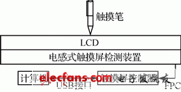
Figure 1 Overall structure of inductive touch screen
1.2 Structure of touch detection device
The touch detection device is composed of a flexible PCB (Printed Circuit Board) with a thickness of 0.8 mm. Two layers of horizontal (Y-axis) vertical (X-axis) vertical crossing wires are embedded inside the PCB, between each group of crossing wires All are insulated; one end of the wire is grounded, and the other end is connected to the input end of the analog electronic switch CD4051 in the touch screen controller through the FPC. The number of coils in the X and Y axis directions is determined according to the size of the display. The structure of the touch detection device is shown in FIG. 2. The X-axis direction of the touch detection device is composed of 35 coils and the Y-axis is composed of 30 coils, which is suitable for 14-inch display screens.
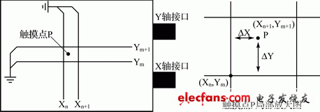
Figure 2 Touch detection device structure
1.3 How to determine the coordinates of the touch screen
When the user approaches the touch pen with the detection device, the detection device will sense the signal, and the touch signal is detected by time-sharing scanning. The right side of Figure 2 is a partial enlarged view of the touch point P. If the point P is touched, electromagnetic signals will be induced on the coils Xn, Xn + 1 and Ym, Ym + 1, making the signal of the detection port change from zero to non-zero zero. First, scan the X-axis direction, scan the signal on Xn through the analog electronic switch, and output it to the OUT terminal from the CD4051 common output pin, and then transmit the signal to the MCU after amplification, filtering, and voltage rectification circuit. The MCU completes the A / D converts to obtain a voltage value Vn; then the signal scanned on Xn + 1 is also amplified, filtered, and rectified, and then the signal is sent to the MCU for A / D conversion to obtain a voltage value Vn + 1. After the scanning in the X-axis direction is completed, the Y-axis is scanned again. Similarly, two voltage values ​​Vm, Vm + 1 can be detected on Ym and Ym + 1, and the four detected voltage values ​​Vn, Vn + 1, Vm can be used , Vm + 1 can calculate the touch coordinates, the calculation formula is as follows:

Among them, Xn, Ym, Xn + 1, Ym + 1 are known coordinates, ΔVx, ΔVy are known constants, ΔVx is the difference between Vn and Vn + 1 when the touch pen is on the Xn axis, and ΔVy is the touch pen The difference between Vm and Vm + 1 on the Ym axis.
The X and Y values ​​obtained from the touch screen controller are only the coordinates of the current touch screen. It has no practical value. This value is not only related to the touch screen resolution, but also related to the fit of the touch screen and LCD [4]. The resolution and coordinates of LCD and touch screen are different. Therefore, if you want to get the position of the touch screen that reflects the coordinates of the LCD, you need to convert it in the program. The conversion formula is as follows:

Among them, LCDWidth, LCDHeight are the width and height of the LCD screen, XLCD_min, XLCD_max and YLCD_min, YLCD_max are the maximum and minimum values ​​of the horizontal and vertical coordinates of the touch screen, respectively.
2 Touch screen control system hardware design
The overall structure of the touch screen control circuit is shown in Figure 3. When the LCD screen is touched with a touch pen, a signal is sensed on the X and Y axes corresponding to the touch detection device respectively. This signal passes through an analog electronic switch, and then undergoes two-stage amplification and filtering, and the resulting signal is processed in two ways. , One way is voltage rectification, the other way is frequency detection circuit; the obtained data is calculated by MCU HT46RB70 to determine the position of the touch screen and the touch mode, and then the MCU sends the touch signal to the computer, and finally realizes touch input. The timing of the entire touch screen control circuit is controlled by the single-chip microcomputer, and the circuits of other modules are described in detail later.
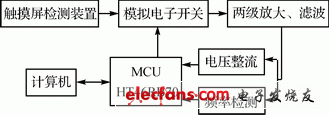
Figure 3 The overall structure of the touch screen control circuit
AURORA SERIES DISPOSABLE VAPE PEN
Zgar 2021's latest electronic cigarette Aurora series uses high-tech temperature control, food grade disposable pod device and high-quality material.Compared with the old model, The smoke of the Aurora series is more delicate and the taste is more realistic ,bigger battery capacity and longer battery life. And it's smaller and more exquisite. A new design of gradient our disposable vape is impressive. We equipped with breathing lights in the vape pen and pod, you will become the most eye-catching person in the party with our atomizer device vape.The 2021 Aurora series has upgraded the magnetic suction connection, plug and use. We also upgrade to type-C interface for charging faster. We have developed various flavors for Aurora series, Aurora E-cigarette Cartridge is loved by the majority of consumers for its gorgeous and changeable color changes, especially at night or in the dark. Up to 10 flavors provide consumers with more choices. What's more, a set of talking packaging is specially designed for it, which makes it more interesting in all kinds of scenes. Our vape pen and pod are matched with all the brands on the market. You can use other brand's vape pen with our vape pod. Aurora series, the first choice for professional users!
We offer low price, high quality Disposable E-Cigarette Vape Pen,Electronic Cigarettes Empty Vape Pen, E-cigarette Cartridge,Disposable Vape,E-cigarette Accessories,Disposable Vape Pen,Disposable Pod device,Vape Pods,OEM vape pen,OEM electronic cigarette to all over the world.
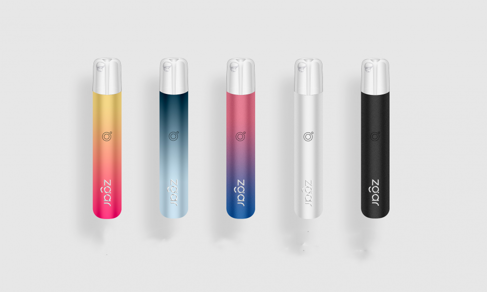
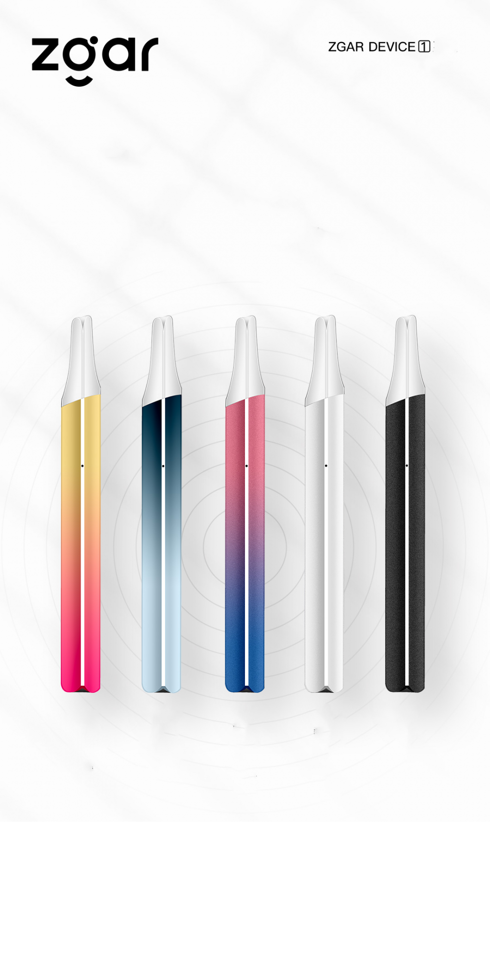
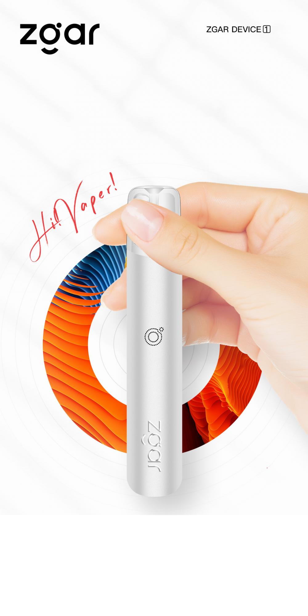
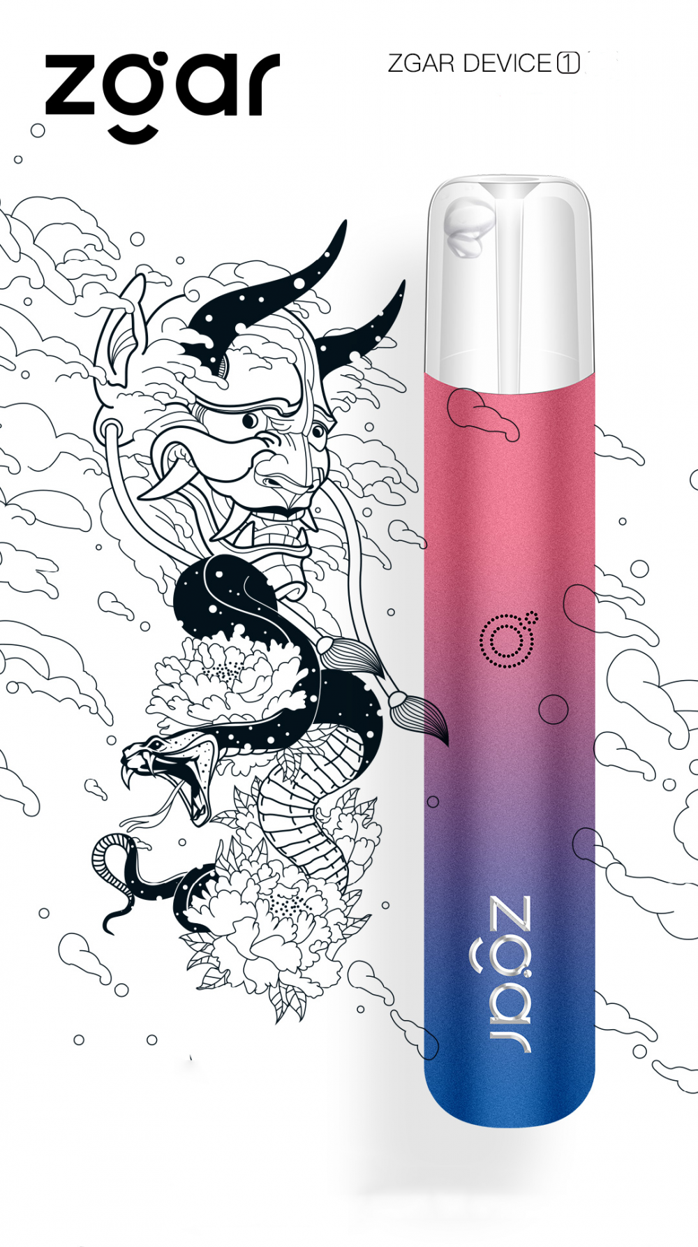
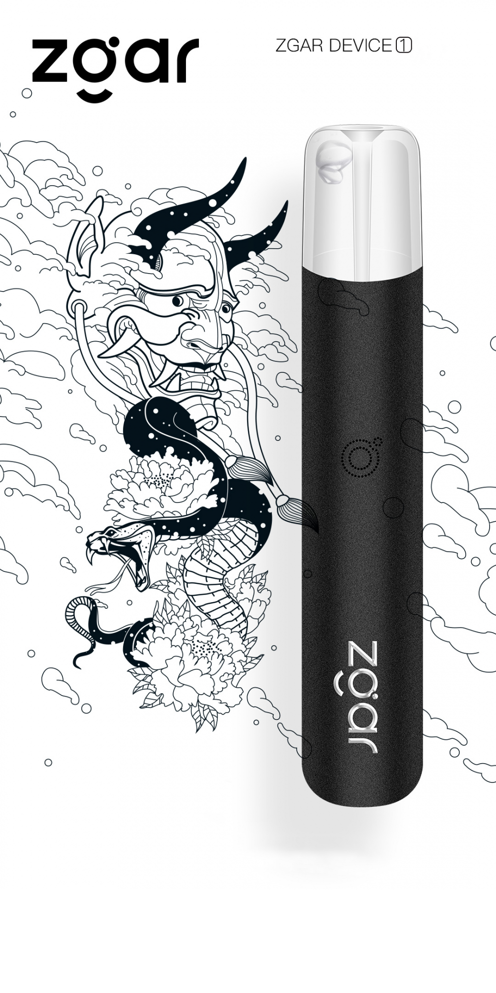
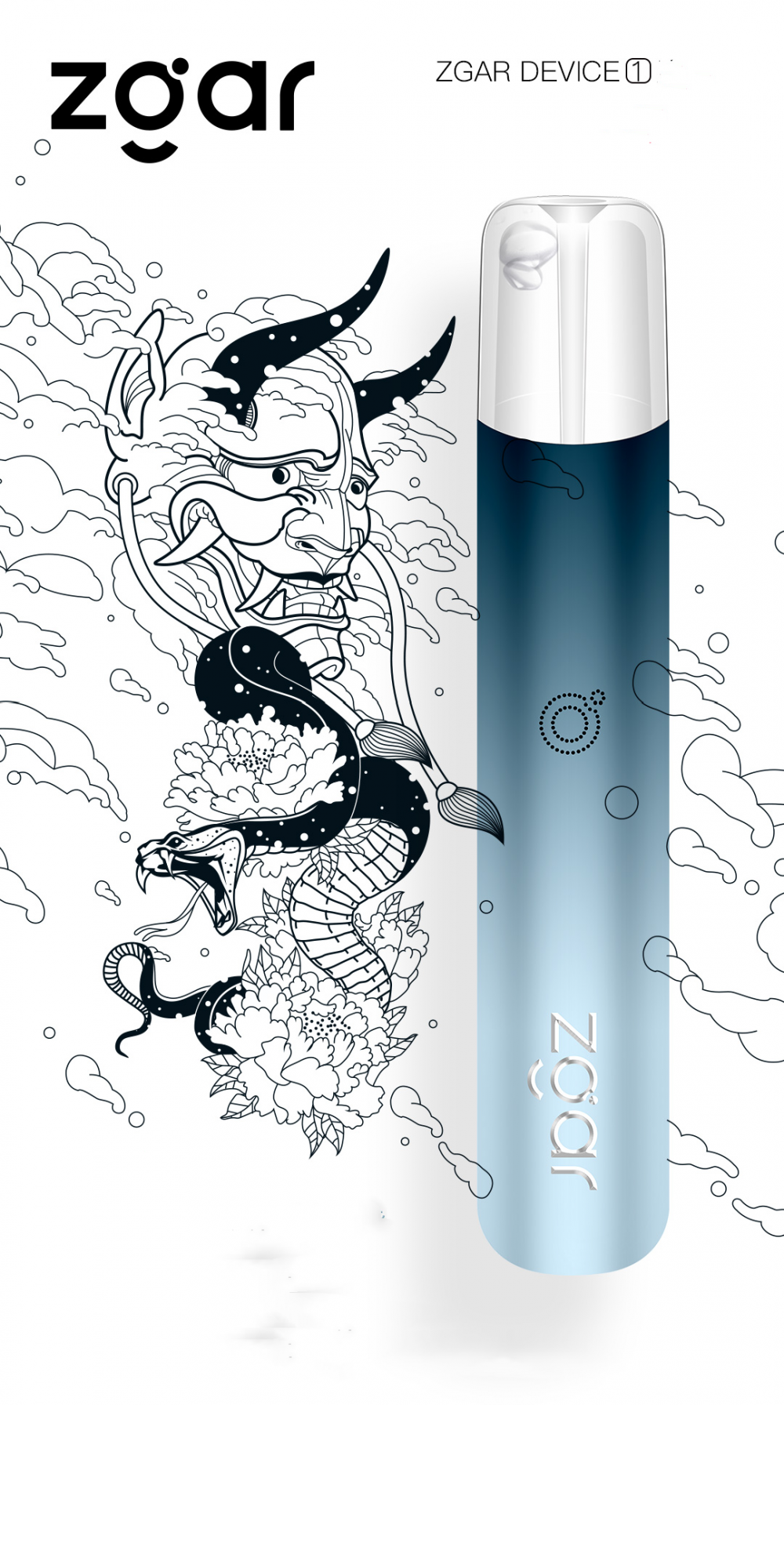
ZGAR Classic 1.0 Disposable Pod Vape,ZGAR Classic 1.0 Disposable Vape Pen,ZGAR Classic 1.0,ZGAR Classic 1.0 Electronic Cigarette,ZGAR Classic 1.0 OEM vape pen,ZGAR Classic 1.0 OEM electronic cigarette.
Zgar International (M) SDN BHD , https://www.oemvape-pen.com