When designing and making the calculator, you need to prepare a piece of 89C52 single-chip microcomputer, 8x8 dot matrix LED display, 16 key switches (or matrix keyboard), and a few capacitors and resistors.
First, the matrix keyboard
The button switch is the most commonly used input component of the MCU. It can be easily read into the switch state of the button through the I/O port of the MCU. If you need to read the status of multiple buttons, then having one I]O port for each button will consume a lot of system resources. A simple solution is to encode the keys, such as the 1st key code 0001, the 2nd key 0010----- so that the four I/O ports can detect the status of 16 keys. However, the encoding method is very limited. Only one button can be pressed at most for all code buttons, otherwise it cannot be encoded. The reason is that the encoder ignores the multi-key state from the 216 switching states of the 16 keys, leaving only 16 single-key states, which improves the resource utilization efficiency. How can I detect all states while saving I/O port resources? A matrix keyboard is a smart choice.
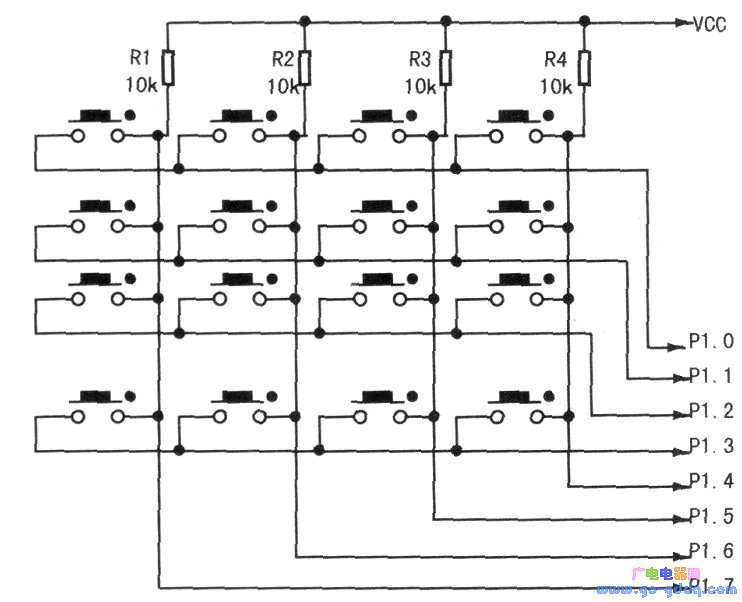
In order to reduce the occupation of the I/O port when the number of keys in the keyboard is large, the keys are usually arranged in a matrix form as shown in the following figure. In a matrix keyboard, each row and column line is not directly connected at the intersection, but is connected by a button. In this way, a port (such as the P1 port) can constitute 4 × 4 = 16 buttons, saving 50% of the 1 / 0 port. For the same reason, 64 buttons require only 16 I/O ports, saving 75%. It can be seen that the more the number of buttons, the more obvious the advantage of the matrix keyboard.
It is relatively easy to judge whether there is a key press in the matrix keyboard. After all the row lines are set to a low level, the state of the column line can be detected. As long as the level of one column is low, it means that there is a key pressed in the matrix keyboard, and the closed key is located in a column of buttons whose low column line intersects the row line. If all of the column lines are high, no key is pressed in the matrix keyboard. The reference procedure is as follows:
iNTCheck_key()∥Check if the button is pressed
Iunsignedcharflag; / / define the flag byte variable
Pl=OxFO;//Set all line lines (P1.O~P1.3) to low level, and P1.4~P1.7 are set to read status.
Flag=Pl;//Read Pl port
If(flag==OxFO)retum(0);//If P1.4~P1.7 are all 1, all column lines are high, no key is pressed in the matrix keyboard.
Elsereturn(l);//Otherwise, a column is low, and a button in the column is pressed
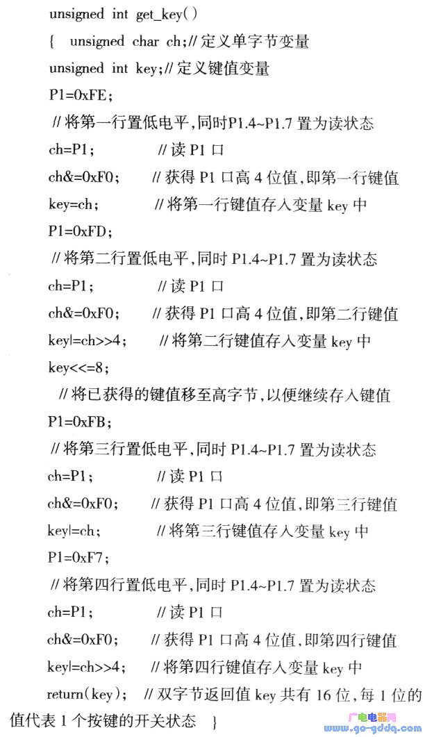
Although the matrix structure is relatively simple, its key recognition is more complicated. Therefore, its savings on hardware resources are at the expense of increased time complexity. To identify the key on the matrix keyboard, press the "scan method": set the row line to low level in turn, that is, when a certain row line is low, the other lines are high. After determining that a certain row line position is low, the level state of each column line is detected line by line. If a column is low, the button at the intersection of the column line and the line line that is set low is the closed button. The reference procedure for scanning which keys of the 4x4 matrix keyboard is pressed is as follows:
Second, the software anti-shake
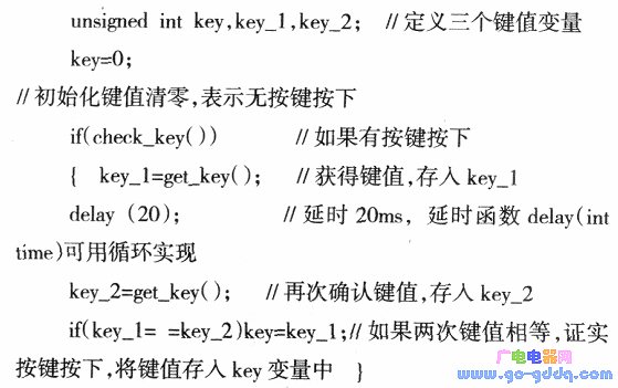
When the mechanical button is pressed or released, it is stabilized by the influence of mechanical resilience, usually accompanied by mechanical vibration of the contact. The length of the jitter time is related to the mechanical characteristics of the switch, which is generally lO~lOOms. A single button can be used to add an RS trigger (bistable trigger) or a monostable trigger at the key output end to form a debounce circuit. When the button is more, the hardware debounce cost is higher and the structure is complicated, and software anti-shake can be adopted: When it is detected that there is a button press, execute a delay program of about 20ms (the specific time should be adjusted according to the used button), and then confirm whether the button level remains at the closed state level, if it remains closed. It is confirmed that the key is in the closed state; similarly, after detecting the release of the key, the same procedure should be used for confirmation, thereby eliminating the influence of jitter. The program fragment is as follows:
Third, the scan display
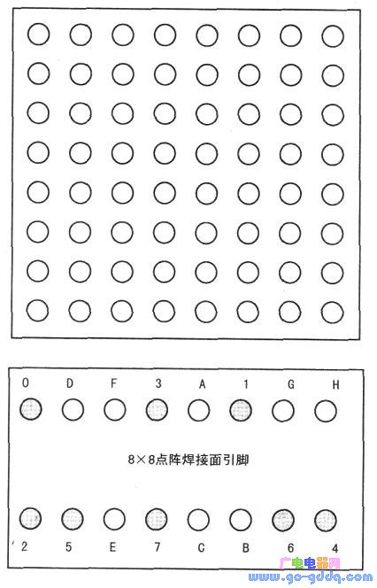
The LED display block is composed of a plurality of semiconductor light-emitting diode pixels arranged uniformly. The most common package structure is 5x7.7x9.8x8. The first two are mainly used to display various Western characters, and the latter one is often used to display various Chinese characters. The appearance of the 8x8 dot matrix LED display block and the pins are as shown. Each circle in the appearance diagram represents a light-emitting diode. These LEDs are connected by a common anode (yin) and a column (yin), and a total of 16 pins are drawn. Among them, 0~7 pins are connected to 8 lines of common anode (yin) line input, and A~H pins are connected to 8 columns of common (yang) input respectively, and display control is performed by inputting high and low levels. The internal structure of the 8x8 dot matrix LED display block is shown below.
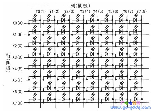
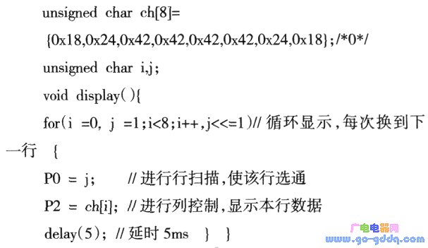
The dot matrix LED display block is scanned and driven by digital logic circuitry. The LED display block arranges the light-emitting lamps in rows and columns, and drives them in rows and columns. In the scan drive mode, you can scan by row and control by column; you can also scan by column and control by row. When scanning, the LED devices of the entire row are cycled one by one, regardless of which column of LED devices in the row should be lit, and whether the LED device of a certain column should be lit is responsible for the column control circuit. The 8x8 dot matrix needs to scan 8 rows for each screen, and 8 pixels per row requires 8 bytes of data. Therefore, each dot of the dot matrix display block is displayed in a line scan to display 8 bytes of data. The scanning speed should not be too fast. Otherwise, the IED will be powered off when it is not fully lit, and the display will not light. If the scanning is too slow, the display will flash. The visual persistence of the human eye lasts approximately O.ls, so the scanning frequency of 25 Hz is generally selected, and the display time per line should be 5 ms. The scan display procedure for the character "0" is as follows:
Fourth, the button echo
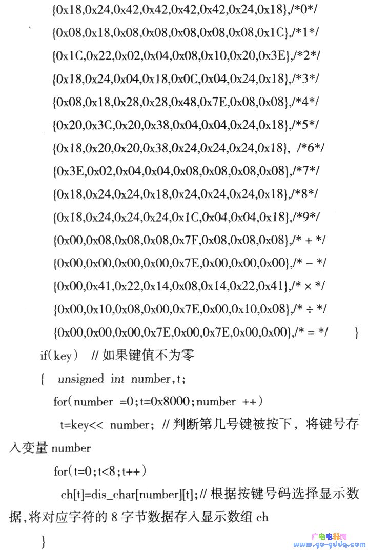
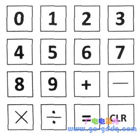
The key echoing means that the symbol represented by the key is displayed after each key press, so that the user can confirm that this is one of the functions commonly used in the humanized design. In this example, there are 16 calculator buttons, and the corresponding characters include 0 to 9 ten digits and 5 mathematical symbols of +, 1, x, ÷, =, and CLR keys, as shown in the following figure. When the number or symbol key is pressed, the MCU should scan its key value and display the corresponding symbol on the dot matrix screen according to the key value. The reference procedure is as follows:
Unsigned char code dis_char[15l[8]={ /*15 symbols display data, the character order is adjusted according to the button settings */
Fifth, data processing
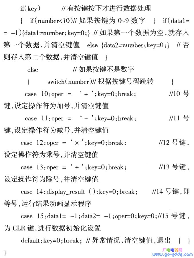
The calculator needs to get two data and one operator first, then perform the required calculations, and finally get the result data. The simple calculator can only process the input data within 10, and the reference program is as follows: (The multi-digit four arithmetic processing program is more complicated, and can be written according to the routine)

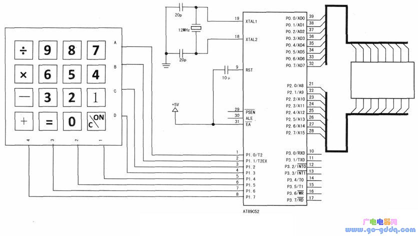
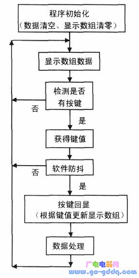
The technical implementation of each part of the simple calculator is introduced in the previous section. However, in order to make the program run smoothly, a reasonable program flow and the correct connection of each part of the interface are required. By the way, the matrix keyboard of the integrated package is equivalent to the cost of 16 buttons. The panel interface is different in variety and can be selected and modified according to the panel. The figure above shows the hardware connection diagram. If there is any problem with the software flow design, please refer to the following figure.
Pod systems e-cigarette offer many advantages over other vaping devices. The main ones are convenience and simplicity. They`re easy to use,
making them more appealing to ex-smokers who don`t want to be bombarded with technical features.
If you want to conserve e-juice, a pod vape is your best bet. They use less e-liquid in a day, which is more cost-effective and
harm-reducing. Additional benefits include their MTL-style draw, not having to build coils, and the other maintenance required for other vapes
pod system e-cigarette pen,pod system e cig,pod system e-cigarette kit,pod system e-cigarette vaporizer,pod system e-cigarette device
Ningbo Autrends International Trade Co.,Ltd. , https://www.mosvape.com