In the existing automobile simulators and automobile driving assessment systems at home and abroad, the state signals of the operating mechanisms of the foot pedals (the accelerator pedal, the foot brake pedal, the clutch pedal) and the handbrake are mainly extracted by installing the angle sensor or The mechanical device converts the rotary motion of the mechanism into a linear motion, and the linear displacement sensor is installed to realize the position state; the position state of the gear position is respectively installed by the switch switch group or the non-contact switch group (Hall switch, photoelectric switch) at different positions of the gear position. The switch quantity signal is obtained, and the position information of the gear position is obtained. Due to the high cost and large volume of these sensors, and the use of multiple sensor types in one vehicle, the specifications of the detection devices are not uniform, which brings great inconvenience to the manufacturing, installation, maintenance and maintenance of the automobile driving state detection system. [1-2].
In recent years, micro-electromechanical systems (MEMS) technology micro-mechanical inertial devices have become increasingly mature, and inertial measurement systems have been rapidly developed [3]. Inertial measurement system combines microelectronics, precision machinery and sensor technology, with higher integration, better cost performance, smaller size and lower power consumption. It is accurate, reproducible and easy to integrate due to micro-mechanical structure. It is suitable for mass production and has a high cost performance. It has been widely used in automobiles [4-5]. Gyro and accelerometer are important components of attitude measurement system. This paper selects ADIS16355 sensor, which integrates three-axis acceleration sensor and three-axis gyroscope sensor. It has small size, strong function and low power consumption. Data collection requirements for vehicle driving motion parameters.
1 measurement system hardware design
1.1 measurement system hardware components
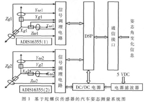
The vehicle driving simulator attitude measurement system is shown in Figure 1. It mainly includes signal acquisition module (gyroscope and signal conditioning circuit), signal processing and transmission module (microcontroller and communication circuit), and power module. 
The signal acquisition module is composed of a MEMS gyro sensor and a signal conditioning circuit, and completes the physical quantity conversion of the inclination change of the vehicle driving operation mechanism such as the throttle, the foot brake, the clutch, the hand brake, the gear position, and completes the reliable transmission of the sensor output signal; the signal processing and The transmission module is composed of DSP to form the core device, which can accurately measure the inclination change of the moving mechanism under the condition of attitude and dynamic acceleration change, complete the digital filtering of the signal, integrate the angular velocity variation into the operation of the angular variation, differential processing and serial output. Waiting for work; the power supply uses car charging generator and vehicle battery, the power supply voltage is between 9V and 30V, and the power supply voltage used by the system equipment is 5V.
This article refers to the address: http://
1.2 MEMS acceleration sensor selection
In this paper, the dynamic angle measurement is performed using a micromachined (MEMS) ADIS16355 gyroscope. The ADIS16355 gyroscope is a multi-axis motion sensor that efficiently combines a three-axis gyroscope with a three-axis accelerometer to measure all six degrees of freedom. The sensor integrates AD's micromechanical and hybrid information processing technology and is a highly integrated solution that provides calibrated digital inertial sensing; an SPI interface and simple output registration structure for simple system interface and programming; single-supply operation At 4.75V ~ 5.25V; 2000g impact bearing capacity. Compared to other off-the-shelf inertial sensors, ADI-
The S16355 is 50 times more accurate and easy to integrate (23mm x 23mm x 23mm Mod package).
1.3 differential measurement method
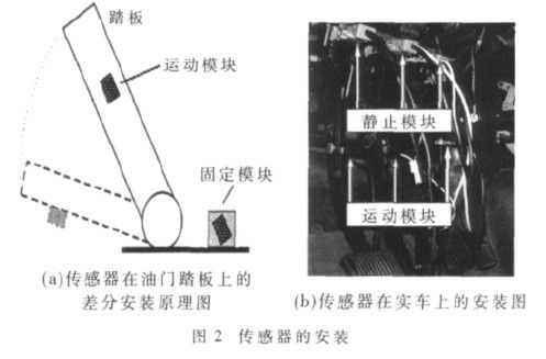
By placing two attitude sensor probes on the object to be measured and the motion carrier on which the object is to be measured, the two attitude sensors have the same attitude in the initial state, and the installation position should be as close as possible so that the two sensors are approximately in a rigid body. At this time, regardless of whether the detection carrier (car) is moving, the detection signals output by the two attitude sensor probes are equal in size, and the differential mode signal is close to zero. When the detecting device is working, two three-axis attitude sensors simultaneously extract three-dimensional motion signals of the measured object and the carrier relative to the ground, and the two sets of signals are combined and processed by the microprocessor to shield the common vibration, moment of inertia, attitude change, etc. The common mode signal retains the differential mode signal of the measured object relative to the moving carrier angle or the cone angle, thereby obtaining the attitude change of the measured object relative to the motion carrier. This method avoids the cumbersome mathematical calculation of data conversion between two reference systems, and has the characteristics of simple circuit and fast signal acquisition and processing [6]. As shown in Fig. 2(a), it is a schematic diagram of the differential installation of the sensor on the accelerator pedal. 
2 software design
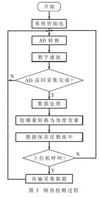
The software of the detection system includes data acquisition and data processing. The software flow chart is shown in Figure 3. According to the installation of the dynamic inclination detecting device, four sets of three-dimensional detection signals (two sets of angular velocity signals and two sets of acceleration signals) on the object to be measured and the dynamic carrier are simultaneously extracted by two modules. The four sets of three-dimensional voltage analog quantity acquisition signals pass through the analog data processing module to shield common mode signals such as vibration, moment of inertia and attitude change, and preserve the differential mode signal of the measured object relative to the moving carrier cone angle, the detection signal Through the arithmetic processing of the DSP, the detection signal outputted by the MEMS gyro sensor and the corresponding angular amount are converted, so as to measure the inclination of the measured object relative to the carrier. 
3 experiments
According to the requirements of differential measurement, the static module is attached to the fixed bracket, and the motion module is fixed on the clutch, the brake and the accelerator pedal (the damping material and the sponge are used as the vibration damping material between the two modules and the rigid structure), and the installation is made The X-axis of the two modules is in the measurement position with the highest measurement sensitivity. Figure 2(b) shows the installation diagram of the sensor on the actual vehicle.
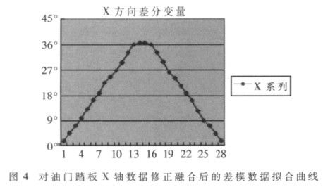
Perform real vehicle experiments on the real car, deliberately let the car body produce the maximum amplitude vibration and attitude change, collect some test data when stepping on the accelerator pedal (taking the accelerator pedal as an example) and then releasing the pedal, respectively using the acceleration information Xg1~ The data of Xg2, angular velocity information X? Brown 1~X? Brown 2 are comprehensively considered and mutually corrected to obtain an optimal estimation value of the vehicle attitude angle. Figure 4 shows the differential mode data fitting curve after the accelerometer and the angular velocity gyro X-axis data are mutually modified. It can be seen that the test results meet the accuracy requirements of the dip signal acquisition of the dynamic car driving operation, indicating the feasibility of the measurement system.
FIG. 4 is a differential model data fitting curve after the accelerator pedal X-axis data is corrected and fused. 
In this paper, the vehicle driving operation signal acquisition system based on ADIS16355 and DSP is designed. The basic idea is to collect the gravity acceleration and angular rate signals, and process the data. Finally, the differential measurement method is used to realize the real-time accurate measurement of the driving state of the car. . The experimental results show that the measurement system can meet the accuracy requirements of vehicle driving operation signal acquisition.
Dongguan Yijia Optoelectronics Co., Ltd. , https://www.everbestlcdlcms.com