Design strategy of blood glucose monitoring system based on MSP430 microprocessor and GSM mobile communication 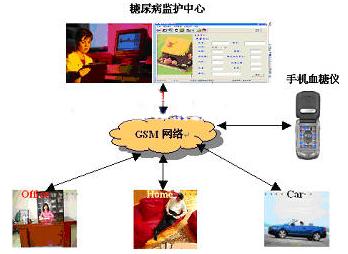

1 Overview of blood glucose monitoring system
Diabetes is one of the four major diseases that endanger human health. At present, there is no cure, and diabetes can only be controlled through blood glucose monitoring. The advent of blood glucose meters has greatly facilitated the self-monitoring of blood sugar by diabetics. In order to make better use of wireless network resources and facilitate users to measure anytime, anywhere, a blood glucose monitoring system based on mobile communication was developed.
The blood glucose monitoring system based on mobile communication is composed of two major parts: mobile phone blood glucose meter and diabetes monitoring center. The working mode is shown in Figure 1. Diabetes patients can monitor the blood glucose at any time by using the mobile phone blood glucose meter they carry. The monitoring center receives the patient's blood glucose value through the GSM network and feeds back the appropriate diagnosis conclusion.

Figure 1 System working mode
The mobile phone uses MotorolA388c. The blood glucose meter is a blood glucose tester based on MSP430 MCU and enzyme electrode sensor independently developed by the School of Instrumentation of Jilin University. It is connected to the mobile phone through a serial port and uses the keyboard and LCD screen of the mobile phone to control and display the blood glucose test results. That is, the mobile phone blood glucose meter adds the blood glucose test function on the basis of retaining the original functions of the mobile phone.
The hardware of the diabetes monitoring center is composed of a server connected to an MC35 wireless communication module through a serial port, and the software system is mainly responsible for controlling the MC35 to receive SMS and patient information management and maintenance.
2 Design of mobile blood glucose meter
2.1 System hardware design
The blood glucose tester based on MSP430 MCU is mainly composed of enzyme electrode sensor, signal processing, MCU data acquisition and processing, and serial communication between MCU and mobile phone, as shown in Figure 2. The enzyme electrode sensor adopts a three-electrode system, which is divided into a reference electrode, a counter electrode and a working electrode.

Figure 2 Mobile phone blood glucose meter system block diagram
The pre-signal processing uses an analog switch to control the electrode access circuit to provide different working conditions for the system. The signal processing uses an amplifier and low-pass filtering to convert and amplify the current signal of the sensor to filter out high-frequency interference, which is the subsequent circuit The data collection of the system provides high-quality signals. The data collection and processing of blood glucose concentration and serial data communication are completed by using TI's MSP430 series single-chip microcomputer as the main control unit. In addition, the system has a temperature compensation function, which can compensate for the error of the ambient temperature on the system test results and improve the accuracy of the test results. The volume of the blood glucose test module is 3cm * 1cm, so it can be placed in the mobile phone case, so that the blood glucose tester and the mobile phone are integrated, which is convenient for the user to carry and detect.
2.2 Measuring principle of blood glucose concentration
The blood glucose concentration value is determined by the bioenzyme electrode sensor. When blood is dropped, under the catalytic action of glucose enzyme, the electron-transporting substance is forcibly oxidized on the surface of the carbon electrode, and the oxidation current formed during the redox reaction is proportional to the glucose concentration. Linear relationship, calculate the blood glucose concentration value by measuring the intensity of the oxidation current [1].
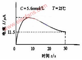
When a constant working voltage of 0.4V is applied to the electrode, when the blood sample to be tested drops in the test area of ​​the electrode, the glucose oxidase fixed on the electrode reacts with the glucose in the blood sample. After a certain lag period, the response current of the enzyme electrode will have a linear relationship with the glucose concentration in the measured blood sample, as shown in Figure 3.

Fig. 3 Current curve of enzyme electrode
Corresponding to the blood glucose concentration of 2.2-27.8mmol / L, the response current of the enzyme electrode is about 3-50μA. The blood glucose meter calculates and displays the glucose concentration value of the blood sample through this corresponding relationship. According to the curve, the reaction current on the enzyme electrode peaks at around 11s. Therefore, the system sets the first 11s as the reaction time of the enzyme electrode, and the next 5.3s as the collection time of the enzyme electrode. Integrate the current area of ​​5.3s to obtain the electric quantity Q, and then according to the known blood glucose concentration C0, the standard coefficient K can be obtained from the formula:
Q = ∫I (t) dt = K C0
K = Q / C0
So as to find the tested blood glucose concentration:
Cx = Q / K
Temperature is one of the important factors affecting the activity of enzymes and the speed of enzyme-catalyzed reaction [2]. Therefore, to ensure the accuracy of the measurement, temperature compensation must be performed. The temperature compensation formula obtained through system testing and related result analysis is as follows:
Kt = 0.0133t + 0.067
Taking into account temperature compensation, therefore, the formula for calculating blood glucose concentration is as follows:
Cx = Q / (K & TImes; Kt)
2.3 Communication software design
Java mobile phone operating systems all support the standard J2ME MIDP1.0 Java standard. J2ME is a development platform for embedded consumer electronics products launched by SUN. Motorola388, A388C and other mobile phones produced by Motorola not only support the standard J2ME MIDP1.0 Java standard, but also introduced the Motorola SDK for J2ME, which implements some interface functions provided by CLDC / MIDP [3].
The mobile phone and the blood glucose meter are connected through a serial port, so using the mobile phone to receive the data sent by the blood glucose meter correctly and in real time is the key. After many experiments, the multi-threaded development mode can accurately and quickly read the data sent by the blood glucose meter to the mobile phone.
When writing serial communication programs, you need to use the Connector class and StreamConnecTIon, InputStream, and OutputStream interfaces in the javax.microediTIon.io package. All connections in J2ME are established using the open (String connect) method of the Connector class. Different connections can be achieved by passing different parameters connect [4, 5, 6, 7, 8].
2.4 Running on MotorolaA388
Basically follow the following 5 steps:
(1) Packaging: After compiling, use the Archive Builder item in the JBuilder Wizard menu, select Archive type as MIDlet, and follow the prompts to complete the packaging.
(2) Run on PC: run MIDlet, update package files: .jar and .jad files.
(3) Download: Connect the mobile phone to the serial port of the PC with the data cable provided by the mobile phone, select the "download via data cable" menu option on the mobile phone, and then download a free download tool called pcjal.exe through Motorola 388. Easily download MIDlet to your phone.
(4) Installation: After a mobile phone downloads a J2ME program, it will be automatically installed. Store the program in the specified location of the phone.
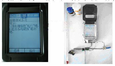
(5) Run on MotorolaA388C: After the program is installed, the phone will display the application in the program menu, and the user can run the program after selecting the menu item. The interface is shown in Figure 4.

Figure 4 running interface
3 Design of Diabetes Monitoring Center
The hardware part of the diabetes monitoring center is mainly composed of a server connected to a GSM module. The wireless module MC35 [9] of SIEMENS is selected. The hardware circuit is mainly divided into four parts: power circuit, used to provide 6V-12V power supply; serial circuit, used to connect with the computer serial port; SIM card circuit, used to connect the SIM card and the module; MC35 module drive circuit, Used to ignite and drive the MC35 wireless communication module.
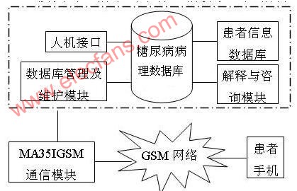
The software system is shown in Figure 5. Among them, the human-machine interface module also adds the function of manually inputting data by the user; the diabetes pathology database includes a knowledge base and a rule base, which stores and manages expert experience and knowledge about diabetes diagnosis, and the rule base is used to store diabetes diagnosis And differential diagnosis rules; the patient information database is used to store the patient's blood glucose measurements and some background information. The communication between the system and GSM module adopts serial communication protocol, and the SMS management uses AT command [10].

Figure 5 System functional block diagram
4 Results and discussion
The mobile blood glucose meter is easy to operate. During the test, the user enters the blood glucose test interface (as shown in Figure 4), clicks the run button, the screen will prompt to insert a blood sample test paper, and then the 15S countdown state will appear, and the blood glucose concentration will be displayed when the countdown is "0" Test results, the test results can be directly clicked on the send SMS button, sent to the MA35I through the GSM network, and then the remote diabetes diagnosis system receives the storage and gives the diagnosis conclusion and feeds back to the patient.
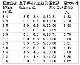
At present, the most accurate measurement method is the hospital's venous blood collection test, but it requires patients to draw a large amount of venous blood, so compared with the system's blood glucose meter, the Johnson & Johnson blood glucose meter with relatively accurate measurement was selected. The absolute error values ​​are given in Table 1. The maximum relative error value.
Table 1 Measurement results and error values

It can be seen from the test results that the maximum repeatability error of the mobile phone-based blood glucose meter is 1.01%, and the maximum relative error of the concentration is 5.98%, which is within the error range of the medical device regulations. Therefore, it is considered that the self-developed mobile phone-based blood glucose tester meets standard.
After the test of sending and receiving short messages, the system is operating normally; the measured data is compared with that in the knowledge base. According to simple rules, the diagnosis conclusion can be automatically given, or the doctor can modify or add suggestions.
In the later period, we will continue to improve the system, and on the basis of the merger system, continue to monitor and study other physiological parameters of the human body, such as blood pressure, pulse, ECG, etc., use wireless and wired connections to store data to the remote medical center server, and Using artificial neural networks and other technologies to carry out individual disease prediction and disease classification.
In the days of rapid development of mobile devices and modern medicine, the operation is simple and convenient, and the cooperation of portable mobile monitoring devices and remote medical centers is the development trend of medical instruments. This article based on the Java mobile phone to achieve serial communication with the blood glucose meter in multi-threaded mode, using the mobile phone to display the stored measurement results, and send it to the remote server in the form of SMS, so as to get expert advice and treatment options. With the rapid development of embedded technology and wireless network technology in the future, mobile medical instruments will have broader application and market prospects.
21-75Kva Diesel Generator,Portable Type Diesel Generator,Home Use Diesel Generator,Shanghai Power Generator Set
Shanghai Kosta Electric Co., Ltd. , https://www.ksdpower.com