Author: Øivind Loe, Silicon Labs Microcontrollers senior marketing manager
Even in the event of a dominant power consumption such as a wireless connection for IoT applications, allowing as many processes to run autonomously can greatly increase battery life. Reducing power consumption has been a major focus in the microcontroller ( MCU ) market. Ultra-low-power MCUs can now significantly reduce power consumption in both operating mode and deep sleep mode. The effect of this change is obvious, it greatly increases battery life in our everyday embedded applications and provides the possibility to use energy harvesting in the future.
However, to reduce power consumption based on the new MCU, developers must take into account a number of factors, in particular, this Silicon Labs writing a technical article: "Run your embedded system with 0 MIPS", to help developers understand how to use the new MCU foreign The autonomous operation is designed to achieve the low power consumption promised in the data sheet by operating closer to "0" MIPS .
Low power consumption is the key to embedded system development
For new MCUs and wireless MCUs ( WMCUs ) used in power-sensitive Internet of Things ( IoT ) applications, power consumption during code execution has dropped significantly, even below 40μA/MHz . With these low-power specifications, you might wonder why we need sleep mode, why not run your code at 500 kHz to achieve 20μA current consumption, and allow your application to run on battery for 10 years? In fact, things are not that simple.
Power consumption in sleep mode has also improved significantly over the past few years. We can now see that the power consumption in deep sleep mode is less than 2μA , while the power consumption in some sleep modes is even lower than 50 nA . You may feel that the power consumption of systems designed with these modes is naturally low, but this is not the case. Whether the application can take advantage of sleep mode is the key.
Why is the working mode good? It is also bad.
The most straightforward way to use an MCU or WMCU is to let the CPU manage everything. For example, you can start an analog-to-digital conversion ( ADC ), put some data into a communication interface (such as a USART transfer), read the ADC data, and do some processing on the data, all directly controlled by the CPU . Direct CPU control simplifies development, but at a cost: whenever a peripheral or external event needs to be processed, the MCU will be in active mode, resulting in a significant increase in power consumption.
Recently, some data sheets show that the operating mode current is 40μA/MHz or lower. They are usually parameters at high clock frequencies, which become larger at low frequencies, which leads to an increase in absolute power consumption. This is because the frequency and power consumption are not linear in the operating mode. Power consumption consists of two parts, the second part of which is not closely related to frequency:
1. The processor itself, which is proportional to the frequency.
2. Modules with basic operating current, such as low dropout linear regulator ( LDO ), undervoltage detector ( BOD ), etc.
To reduce power consumption, you should minimize the MCU 's operation in high-power mode, shut down the peripherals as much as possible , and let the CPU sleep as much as possible.
Power budget
For energy-constrained battery-powered applications, know where energy consumption can be optimized. Table 1 shows a sensor that detects the power budget of a wireless application, and its power optimization is not very good.
The power consumption is measured or estimated by averaging the power consumption of each component. If the CPU duty cycle is two percentage points and operates at 20 MHz at 60μA/ MHz , the CPU consumption is 24μA .
Please note that the power budget shown in Table 1 is based on functionality. For example, the underlying sleep current includes a low frequency oscillator and a real time clock ( RTC ) to time system events to allow for deep sleep.
The sensor measurement section is triggered by a 0.5kHz interrupt, which interrupts deep sleep. Low-power Bluetooth sends out data every second, which is a very common low-power application. Finally, there are some power consumption in the non- MCU part. The MCU may not be able to directly control some of these modules, including power management peripherals. In this example, the MCU directly controls the ADC to sample the sensor. If not, the sensor current will be exactly the data in the picture.
For this example, the sensor's continuous current is approximately 390μA , but by adjusting the duty cycle, each ADC sample is only used for 10 μs , which can greatly reduce power consumption.
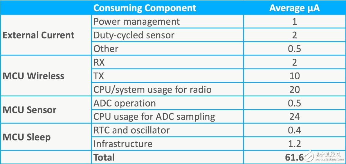
Table 1 Power consumption budget of the target application
If the wireless application is powered by a CR2032 battery with 225 mAh capacity , its lifetime is approximately 0.4 years when operating at 61.6 μA power . In fact, we can do better.
Improve the situation
Let's take a look at ways to reduce the current measured by the MCU sensor. While this example involves ADC measuring external sensors, related examples may focus on a range of different types of measurements and interactions with external environments. In both cases, frequent interactions occur between the MCU and the external environment.
The easiest way to achieve low-power sensing is to put the CPU in sleep mode as much as possible, wake up only during sampling, and return to sleep mode as quickly as possible. This method works well for very low sample rates, but as you can see from Figure 1 , when the number of samples per second increases, the power consumption of the system increases significantly:
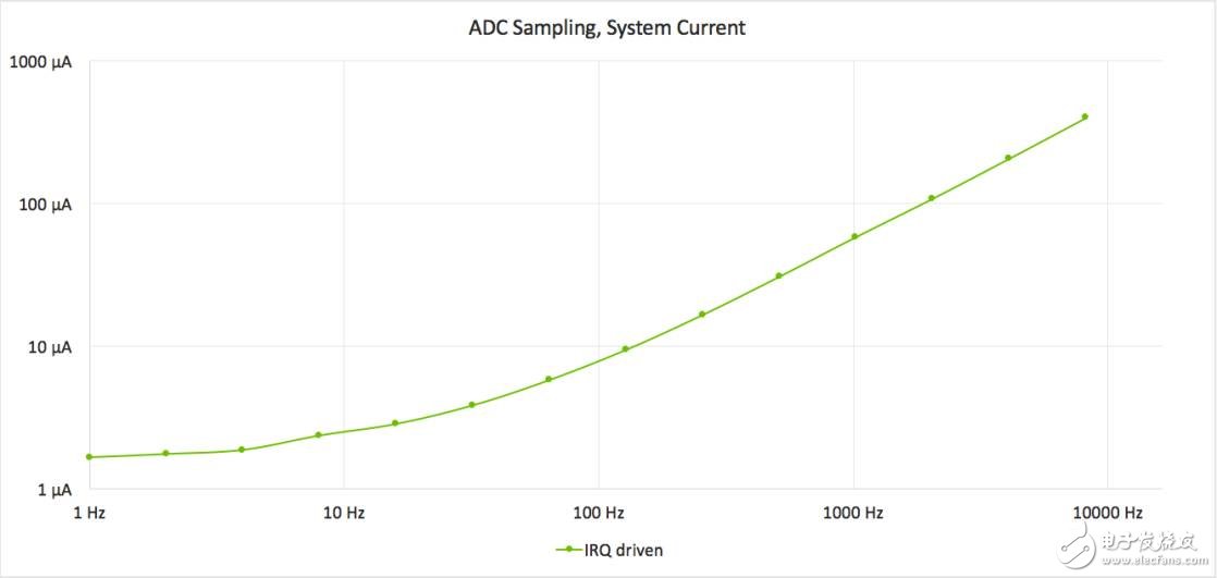
Figure 1 uses an interrupt for ADC sampling, showing that as the number of samples per second increases, power consumption also increases.
Many types of applications must have frequent activities while still maintaining battery life. Activity rates above 1 kHz are not unheard of, and measures are needed to maintain low power consumption.
Figure 2 shows two additional methods of sensor management. The Peripheral Reflection System / Direct Memory Access ( PRS / DMA ) method allows the CPU to sample the ADC in deep sleep mode with no involvement at all . Rather than the RTC wake up the CPU , then the CPU starts the ADC for sampling. The RTC sends events directly to the ADC via an event system such as Silicon Labs ' PRS . The ADC automatically initiates an ADC conversion when it receives this event . After the conversion is complete, the DMA can also run from deep sleep mode in this case, fetching data from the ADC and storing it in RAM . The benefit of the PRS / DMA approach is a significant reduction in current consumption. At 1 kHz , the system current is reduced from 58μA to 25μA .
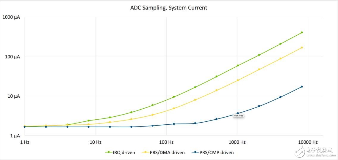
Figure 2 This ADC sample plot shows power consumption in various modes of operation.
A more efficient method of driving an ADC is the PRS/ Comparator ( CMP ) method, in which the RTC still triggers the ADC through the PRS system , but in this case, the ADC immediately evaluates the sample using the compare function, unless the required data is found, Otherwise do not use DMA or CPU . This method enables a system current of only 3.5μA at a 1 kHz sampling rate .
Dynamic ADC comparator
With the PRS/CMP method, most of the sampled data is discarded, and the CPU only focuses on the data that needs to be processed. This method is effective when the signal changes slowly or when a specific signal is required.
When using the compare function to monitor the signal, one method is to measure the signal and then set the threshold based on this signal. As long as the signal is within the threshold range , the system can remain in deep sleep mode when the ADC measures the signal, and of course the CPU remains in sleep. mode.
However, if the signal changes and the threshold is exceeded, the system will know the signal and take the appropriate action. Before returning to sleep mode, the ADC threshold will be reconfigured to accommodate the new signal value, so the system can go into sleep mode again until the next signal changes. Figure 3 shows an example of this technique. The dot represents the ADC sample and the arrow indicates that each time the CPU wakes up, it will record this change and reconfigure the threshold.
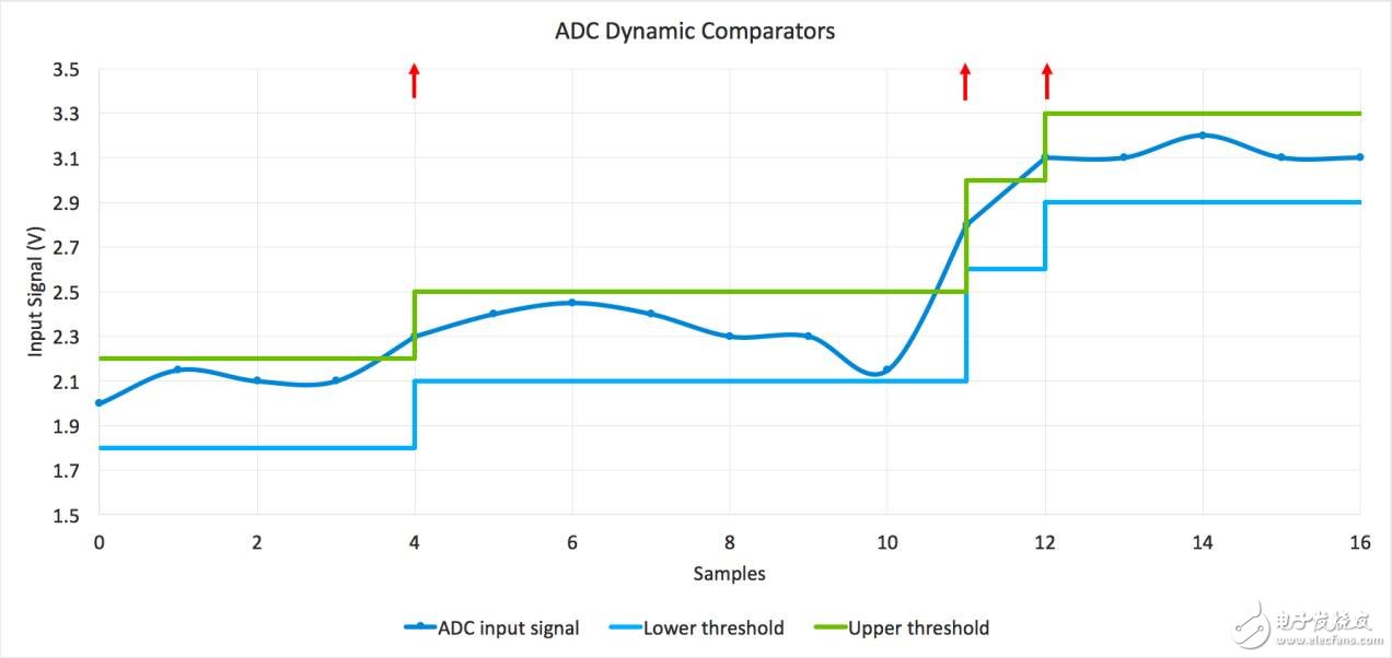
Figure 3: When the signal exceeds the threshold, the CPU interrupt dynamically modifies the threshold of the ADC .
Using this approach, the system will actually lose some signal accuracy because the signal can move arbitrarily within the threshold range between flip-flops. However, the benefit is a significant reduction in power consumption.
If the goal of the system is to measure the dynamic value of the signal, the PRS/DMA drive method is ideal because it makes all the data available while still providing very beneficial energy-saving features.
Autonomous working subsystem
The ADC example is just one of many ways to reduce application power consumption through sleep mode. New MCUs focused on low-power applications (such as Silicon Labs ' EFM32 Gecko MCU ) have a number of features that can operate in deep sleep mode for a high level of autonomous behavior.
For example, the Gresso MCU 's LESENSE (Low Power Sensing) module automatically and periodically samples up to 16 channels without the need for CPU involvement. It can achieve high frequency detection and can work for 10 years with 1 charge .
In many cases, a single peripheral can perform its duties autonomously, but there are many situations in which interaction is required. In this case, we can use peripheral interconnects such as the PRS system found in some of the newer MCUs . These peripheral interconnects allow multiple peripherals to connect to perform more complex tasks autonomously.
Figure 4 shows an example of an autonomous system that uses an event chain to perform its functions:
1. Â Â Â Â Â The RTC periodically transmits a PRS signal to the ADC at a given time to initiate the conversion.
2. Â Â Â Â Â The RTC simultaneously activates the external sensor so that the signal is ready for measurement.
3. Â Â Â Â Â The ADC completes the sampling and notifies the DMA that the DMA transfers the data to RAM .
4. Â Â Â Â Â The completed PRS signal from the ADC turns off the external sensor.
5. Â Â Â Â Â When the buffer is full interrupt wake-up CPU, or ADC interrupt wakes up the CPU exceeds a threshold value.
6. Â Â Â Â Â Optional: The PRS watchdog monitors the event loop to ensure it remains operational.
The DMA can be removed from the system shown in Figure 4 to save power by setting the compare function of the ADC .
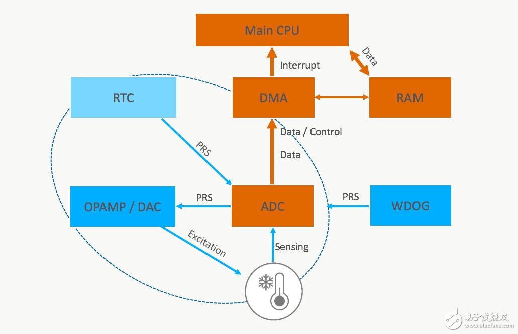
Figure 4. The autonomous ADC system contains periodic working sensors and watchdogs.
These autonomous subsystems have several major advantages:
1. Â Â Â Â Â Significant energy savings.
2. Â Â Â Â Â The sensor can still work stably even when the CPU load is heavy.
The downside is that not all MCUs support this type of operation, and when setting up interactions, you'll want to think like a hardware designer. In summary, for many battery-powered applications, the benefits are significantly more than the disadvantages.
in conclusion
By utilizing various energy-saving technologies, the CPU is almost completely out of work when the sensor is measured . For the wireless application shown in Table 1 , this will reduce the total average power consumption from 61.6μA to 37.6μA , a 39 % reduction , thereby extending battery life from approximately 5 months to 8 months, an increase of 64 %, or The battery size can be allowed to be reduced to improve the system shape.
For non-wireless applications, energy savings will be more significant. Example in Table 1, to reduce energy consumption from 29.6μA 5.6μA, powered by a battery CR2032, will theoretically extend the life of 10 months to 4.6 years.
If you want to learn more embedded courses, please scan the QR code below and learn now!

ZGAR LEA BOX Disposable
ZGAR electronic cigarette uses high-tech R&D, food grade disposable pod device and high-quality raw material. All package designs are Original IP. Our designer team is from Hong Kong. We have very high requirements for product quality, flavors taste and packaging design. The E-liquid is imported, materials are food grade, and assembly plant is medical-grade dust-free workshops.
Our products include disposable e-cigarettes, rechargeable e-cigarettes, rechargreable disposable vape pen, and various of flavors of cigarette cartridges. From 600puffs to 5000puffs, ZGAR bar Disposable offer high-tech R&D, E-cigarette improves battery capacity, We offer various of flavors and support customization. And printing designs can be customized. We have our own professional team and competitive quotations for any OEM or ODM works.
We supply OEM rechargeable disposable vape pen,OEM disposable electronic cigarette,ODM disposable vape pen,ODM disposable electronic cigarette,OEM/ODM vape pen e-cigarette,OEM/ODM atomizer device.


Disposable E-cigarette, ODM disposable electronic cigarette, vape pen atomizer , Device E-cig, OEM disposable electronic cigarette
ZGAR INTERNATIONAL TRADING CO., LTD. , https://www.zgarvapepen.com