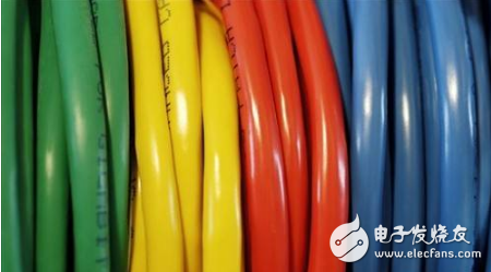
The English name for the twisted pair is Twist-Pair. It is the most commonly used transmission medium in integrated wiring engineering and consists of two copper wires with an insulating protective layer. The two insulated copper wires are twisted together at a certain density, and the electric wave radiated by each wire in the transmission is cancelled by the electric wave emitted from the other wire, thereby effectively reducing the degree of signal interference.
The twisted pair cable uses a pair of mutually insulated metal wires to twist each other to resist some external electromagnetic interference. By twisting two insulated copper wires together at a certain density, the degree of signal interference can be reduced, and the electric wave radiated by each wire during transmission can be cancelled by the electric wave emitted from the other wire. The name "twisted pair" is also derived from this.
The twisted pair cable is generally formed by two 22-26 insulated copper wires intertwined. In actual use, the twisted pair cable is wrapped in an insulated cable sleeve by a plurality of pairs of twisted pairs. Typical twisted pairs have four pairs, and more pairs of twisted pairs are placed in a cable jacket. This is what we call twisted pair cable. In a twisted pair cable (also called a twisted pair cable), different pairs have different twist lengths. Generally speaking, the twist length is within 38.1 cm to 14 cm and is twisted counterclockwise. The twist length of the adjacent pair is above 12.7cm. The denser the twisted wire is, the stronger the anti-interference ability is. Compared with other transmission media, the twisted pair is in terms of transmission distance, channel width and data transmission speed. Subject to certain restrictions, but the price is relatively low.

The following is a brief introduction to the line sequence standards and main indicators of twisted pairs.
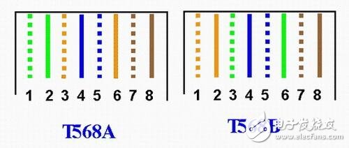
Twisted pair line order standardIn North America, the three most influential integrated wiring organizations in the world are as follows. ANSI (American NaTIonal Standards InsTItute, American National Standards Institute) TIA (Telecommunica TIon Industry Association, EIA (Electronic Industries Alliance, American Electronic Industry Association). Since the TIA and ISO organizations often coordinate the development of standards, the differences between the standards issued by TIA and ISO are not very large. In North America, and globally, the most widely used twisted pair standards are ANSI/EIA/TIA-568A and ANSI/EIA/TIA-568B (actually ANSI/EIA/TIA-568B.1, referred to as T568B) ). The main difference between the two standards is the difference in core sequence:

The line order definition of EIA/TIA568A is green white, green, orange white, blue, blue white, orange, brown white and brown. The labels are as follows:

The line order definition of EIA/TIA568B is orange white, orange, green white, blue, blue white, green, brown white and brown, and the labels are as follows:

According to the 568A and 568B standards, the contacts of the RJ-45 connector (commonly known as the crystal head) are in the network connection, and they play a role in transmitting signals: 1, 2 for transmission; 3, 6 for receiving ; 4, 5, 7, 8 are bidirectional lines. For the twisted pair connected to it, in order to reduce mutual interference, the standard requirements 1, 2 must be a pair of twisted wires, 3, 6 must also be a pair of twisted wires, 4, 5 are twisted with each other, 7, 8 entangled with each other. It can be seen that there is no essential difference between the two standards 568A and 568B, except that the line sequence of 8 twisted pairs is different when RJ-45 is connected, and the 568B standard is used in actual network engineering construction.
Main indicators of twisted pairFor twisted pairs, the user is most concerned with several indicators that characterize their performance. These indicators include attenuation, near-end crosstalk, impedance characteristics, distributed capacitance, and DC resistance.
Attenuation
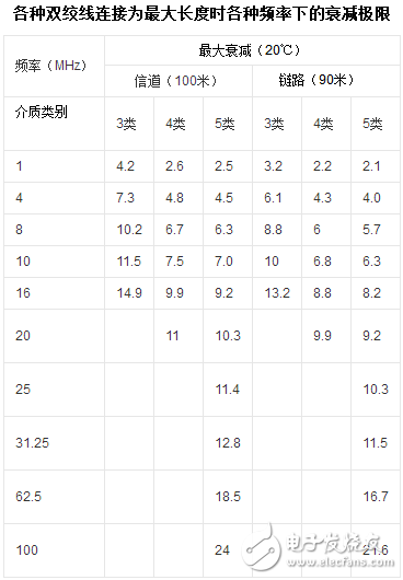
Attenuation is a measure of signal loss along the link. Attenuation is related to the length of the cable, and as the length increases, the signal attenuation increases. The attenuation is expressed in units of "db", which represents the ratio of the signal strength of the source transmitting end to the signal strength of the receiving end. Since the attenuation varies with frequency, the attenuation over all frequencies within the application range should be measured.
2. Near-end crosstalk
Crosstalk is divided into near-end crosstalk and far-end crosstalk (FEXT). The tester mainly measures NEXT. Because of the line loss, the influence of the magnitude of FEXT is small.
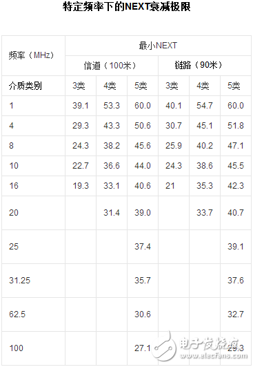
Near-end crosstalk (NEXT) loss is the measurement of signal coupling from one pair of wires to another in an unshielded twisted pair link. For unshielded twisted pair links, NEXT is a key performance indicator and one of the most difficult to measure accurately. As the signal frequency increases, the measurement difficulty will increase. NEXT does not represent the crosstalk value produced at the near endpoint, it simply represents the crosstalk value measured at the near endpoint. This magnitude will vary with cable length, and the longer the cable, the smaller its value becomes. At the same time, the signal at the transmitting end is also attenuated, and the crosstalk to other pairs is relatively small.
Experiments have shown that only the NEXT measured within 40 meters is more realistic. If the other end is an information outlet that is more than 40 meters, it will generate a certain degree of crosstalk, but the tester may not be able to measure the crosstalk value. Therefore, it is best to perform NEXT measurements at both endpoints. Most testers are equipped with appropriate equipment so that the NEXT values ​​at both ends can be measured at one end of the link. The results of the NEXT test refer to the following table:


The above two indicators are the main content of the TSB67 test, but some models of the tester can also give indicators such as DC resistance, characteristic impedance, and attenuation crosstalk ratio.
3. DC resistance
The DC loop resistor consumes a portion of the signal and converts it into heat. It refers to the sum of a pair of wire resistances. The DC resistance of the 11801 specification twisted pair shall not be greater than 19.2 ohms. The difference between each pair should not be too large (less than 0.1 ohms), otherwise it means poor contact and the connection point must be checked.
4. Characteristic impedance
Unlike the loop DC resistance, the characteristic impedance includes the resistance and the impedance of the inductor and the impedance of the capacitor from 1 to 100 MHz, which is related to the distance between the pair of wires and the electrical properties of the insulator. Various cables have different characteristic impedances, while twisted pair cables are available in 100 ohms, 120 ohms, and 150 ohms.
5. Attenuation crosstalk ratio (ACR)
In some frequency ranges, the proportional relationship between crosstalk and attenuation is another important parameter that reflects cable performance. ACR is sometimes also expressed in terms of signal-to-noise ratio (SNR: Signal-Noiceratio), which is calculated from the difference between the worst attenuation and the NEXT magnitude. The ACR value is large, indicating that the anti-interference ability is stronger. General system requirements are at least greater than 10 decibels.
6. Cable characteristics
The quality of the communication channel is described by its cable characteristics. SNR is a measure of the strength of a data signal, taking into account interfering signals. If the SNR is too low, it will cause the receiver to be unable to resolve the data signal and the noise signal when the data signal is received, eventually causing data errors. Therefore, in order to limit data errors to a certain range, a minimum acceptable SNR must be defined.
Strong and durable
Aluminum alloy plug, TPE cover
Hidden design
One second stretch, free storageUltrasonic welding pressure
Close fitting, firm resistance to fall
Strong and durable
Priority TPE
It's hard to break even if you stretch multiple times
Stretching or shrinking only one end can easily to damage the components and cause jamming
No winding
Stretch when used, shrink when not used
Five lengths
Each pause is a length, suitable for multiple occasions
Notice
Both cables are stretched at the same time
Do not stretch unilaterally
Data Cable Wiring,Original Data Cable,Computer Transfer Cable,Line Data Charging Cable
Guangzhou HangDeng Tech Co. Ltd , https://www.hangdengtech.com