Abstract: The Maxim USB library is a software routine based on the MAX3421E / MAX3420E using an ARM7 ™ processor. This application note describes the operation of the system and its software. The USB host and peripheral functions are implemented in the same ARM® C language code. This method allows the development and research of USB peripherals and embedded hosts to have the advantage of having a reference device at the other end of the USB cable, all of which are contained in the same C language code.
This application note is application note 3997, "Building a Maxim USB Library". The Keil â„¢ project containing the Maxim demo program can be downloaded.
Introduction The Maxim USB library is a combination of two circuit boards and C language programs. With this system, you can: research, operate, test, and modify USB-enabled devices based on an ARM7 microcontroller (µC) connected to the MAX3420E USB peripheral controller. Research, operation, testing, and modification of a USB function host based on an ARM7 microcontroller (µC) connected to the MAX3421E USB host controller. Figure 1 shows the data retrieval from the USB stick by the host. Use a USB cable to connect the host to the peripherals and run the host and peripherals at the same time. When developing USB host or USB peripheral code, it is useful to have a reference design on the other end of the USB cable. In this way, both ends of the USB cable, the host and the peripherals are executed the same C language code, so it has controllability and customization.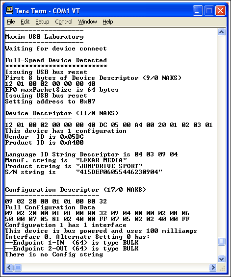
Figure 1. The MAX3421 host / ARM retrieves enumerated data from any USB peripheral and connects to the PC running a terminal emulation program via the serial port to report the results.
Other data programming guides, data sheets, and MAX3420E and MAX3421E application notes provided on the Maxim website:
MAX3420E
MAX3421E
Maxim Application Note AN3937, "Building a Maxim USB Library"
Hardware This application uses C language code to run on two board devices: MAX3421 evaluation (EV) board, the first circuit board Keil MCB2130 board, the second circuit board
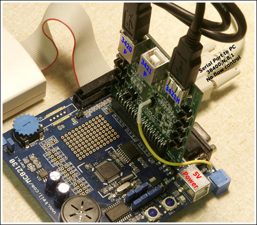
Figure 2. The Maxim evaluation board plugs into the Keil MCB2130 board.
Figure 2 shows the board-level equipment. The blue circuit board is Keil MCB2130, which contains an ARM7 chip, Philips® LPC2138. This microcontroller contains 2 SPI ™ hardware units connected to two Maxim USB control chips.
The erected circuit board is MAX3421EEVKIT-1. A MAX3420E peripheral controller is connected to an SPI port of ARM and wired to the USB "B" connector (J5), labeled "3420 P" in Figure 2 (P stands for peripheral). The MAX3421E host / peripheral controller is connected to another ARM SPI port and wired to the “3421P†(J2) and “3421H†(J1) connectors (H stands for host). The code running in the application uses the MAX3421E as a host, so the USB connector (J2) in the middle of the evaluation suite board is not used.
The host software uses one of the two serial ports (P1 on the MCB2130 circuit board) to send the USB description information to the PC running the terminal emulation program. Terminal programs, such as the Tera terminal program, can emulate the terminal (VT100) and identify the special "transfer code" sequence sent by the program to clear the screen and reset the pointer. The serial port of the terminal program is set to 38400, N, 8, 1, without flow control.
The beige square box and ribbon cable in Figure 2 are Keil ULINK JTAG load-debuggers. The Keil µVision®3 development environment supports this debug unit. The MCB2130 comes with an evaluation version of µVision3, a Keil tool set with a fully functional version. But the evaluation version has a 16kB limit on code capacity.
The attachment of this application note contains the source files of the entire Keil project, as well as the loading module in hex format. If there is a ULINK JTAG unit, the code can be compiled and can be loaded and debugged through the JTAG port. This is an excellent way to quickly develop USB, modify work host and / or peripheral code to make it suitable for development purposes. If you do not have ULINK, you can use a free program called Flash Magic to load and run hex files. This program is available from the website. Refer to Maxim application note 3937 for information on how to configure and use the program.
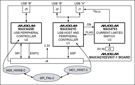
Figure 3. Block diagram of the MAX3421EEVKIT-1 circuit board. The shaded oval is the main software module.
Program Function Figure 3 shows the MAX3421EEVKIT-1 circuit block diagram and the software module of this application note. Both the MAX3420E and MAX3421E use the SPI bus to access their register banks. The LPC2138 contains 2 hardware SPI units: a dedicated SPI port (SPI) and a universal serial interface (SSP, synchronous serial port). The SSP can be programmed to implement a second SPI port. The programming of these ports is different. For example, SSP has 8 transmit and receive FIFOs, while SPI has only 1 read buffer. To be compatible with the MAX3420E and MAX3421E, both SPI interfaces are programmed to work in 8-bit data mode. The software module SPI_FNs.C contains register access functions used by both USB controllers.
The MAX3420E belongs to the SPI unit, so for this chip, the function has a "P" (for example, Prreg and Preg) prefix to indicate the peripheral operation. The MAX3421E belongs to the SSP unit, so its access function has an "H" prefix (such as Hwreg), indicating that it is operated by the host.
The peripheral program C module 3420_HIDKB.C implements a USB peripheral that is connected to a PC by using the connector J5 of the evaluation circuit. The INT output pin of the MAX3420E is connected to the EINT0 (external interrupt 0) pin of ARM7. This interrupt can be triggered at any time when the USB peripheral implemented by the MAX3420E needs to be serviced.
This application lists and implements the standard USD HID (Humanized Interface Device). A major advantage of conforming to the standard Windows® platform is that the device driver is built into Windows, eliminating the need to install a dedicated driver. Windows recognizes the device implemented by this application as a standard keyboard. Pressing any four buttons connected to the MAX3420E GP-IN pin will cause the "keyboard" to enter text strings in any open receive text window, such as notepad and writing pad.
Note: This application can enter text in any text-receiving application, such as e-mail, assembly editor, or Word document. Please make sure there is a safe application before pressing the key, such as notepad is opened and is in a valid state. The author can determine from experience that entering invalid text in an open C source file will not compile completely.
The host code 3241_Host_EVK.C file contains the host code, which enables the MAX3421E to complete certain enumeration steps that are similar to the enumeration steps performed by the PC when a USB device is inserted into connector J4. The main () function in this module is like an interrupt service routine for HID keyboard code. The EINT0 interrupt service routine is as follows: // EINT0 Interrupt handler--MAX3420E INT pin void INT3420 (void) __irq {service_irqs (); // Do the USB thing in 3420_HIDKB_INT_EVK.C module EXTINT = 1; // Clear EINT0 interrupt flag ( b0) VICVectAddr = 0; // Dummy write to indicate end of interrupt service} The basic program main () contains the following infinite loop subroutines:
while (1) {detect_device (); waitframes (200); // Some devices require this enumerate_device (); wait_for_disconnect ();} The Enumerate_device () function completes most of the work, sends a USB request to the connected device, and through the serial port Report the results. Any USB device is plugged into connector J1 of the evaluation board. This function will send an enumeration request to the device and report the result via the serial port (Figure 1).
Synchronous host / peripheral operation Because the MAX3421EEVKIT-1 circuit board contains a USB peripheral and a USB host, and they use a separate SPI interface on the ARM7, the software can be easily written to allow the host and peripheral applications to run simultaneously . The host application runs main () to talk to the MAX3421E in the background, and the HID peripheral code uses the MAX3420E interrupt to activate the service_irqs () function.
If the connectors J5 and J1 of the evaluation board are connected with a USB cable, the ARM processor can act as a USB host to talk to the peripheral, and this peripheral is itself. Figure 4 shows the report of 3421_Host.C's host code querying the peripherals implemented by 3420_HIDKB.C.
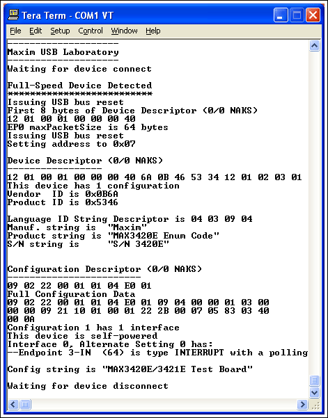
Figure 4. Demonstration of the code for asking itself via USB
Host code development reads through the enumerate_device () function to help understand how the USB host works and also to understand how to command the MAX3421E to complete various host operations when enumerating USB devices. While developing the host code, if the response process of inserting the host into the peripheral is unclear, sometimes it will be difficult to diagnose the problem. If you have reference peripherals in all controls (3420_HIDKB.C module), it will make it easy to find the problem and change the response of the device to test the host hardware.
The peripheral code development host is an excellent query tool for developing USB peripheral code. The combination of the MAX3421E and 3421_Host.C modules produces a simple but powerful USB packet generator and analyzer. By writing C language host code, you can control the peripheral status; MAX3421E displays the peripheral's response process.
The example assumes writing peripheral code to handle USB strings. Write the manufacturer string XYZ Widget Company in the hidkb_enum_tables.h file as follows: // STRING descriptor 1--Manufacturer ID {18, // bLength 0x03, // bDescriptorType = string 'X', 'Y', 'Z ',' ',' W ',' i ',' d ',' g ',' e ',' t ',' ',' C ',' o ',' m ',' p ',' a ',' n ',' y '}, compile the file, load it into ARM's flash memory and run it. The host program will report the following manufacturer string:
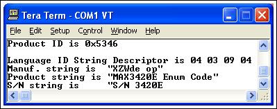
Figure 5. Undesirable result, the routine does not display the manufacturer's name as required, and the code is defective.
What's wrong? It turned out that USB stipulates that text strings are expressed in Unicode, that is, each character is expressed in two bytes. Review the source code of the peripheral, and change as follows: // STRING descriptor 1--Manufacturer ID {35 // bLength 0x03, // bDescriptorType = string 'X', 0, 'Y', 0, 'Z', 0, ' ', 0,' W ', 0,' i ', 0,' d ', 0,' g ', 0,' e ', 0,' t ', 0,' ', 0,' C ', 0 , 'o', 0, 'm', 0, 'p', 0, 'a', 0, 'n', 0, 'y' // Unicode!}, compile and run, you should see:
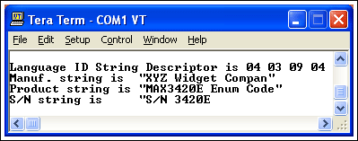
Figure 6. Normal code routine, using Unicode format, you can see the results.
The result has improved, but it is not perfect. Where is the "y" in the company? Carefully count that the string has 35 characters and enter it as the first byte to display the string length. What the design does not pay attention to is that the length byte is also a string, and must contain the first two bytes. The final modification of the code is as follows: // STRING descriptor 1--Manufacturer ID {37 // bLength 0x03, // bDescriptorType = string 'X', 0, 'Y', 0, 'Z', 0, '', 0, 'W', 0, 'i', 0, 'd', 0, 'g', 0, 'e', ​​0, 't', 0, '', 0, 'C', 0, 'o' , 0, 'm', 0, 'p', 0, 'a', 0, 'n', 0, 'y' // Unicode!}, This is what the result should look like:
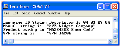
Figure 7. The best code example. The code can now implement what the design wants to achieve.
Through testing the peripheral code and using the host controller and encoding operation / analysis, the reported result is the actual USB message sent from the MAX3420E to the MAX3421E, so you can see the exact same result as the PC response. The best thing is that these can be implemented on a controllable basis, so there is no need to worry about how the PC responds to make code development errors.
Code description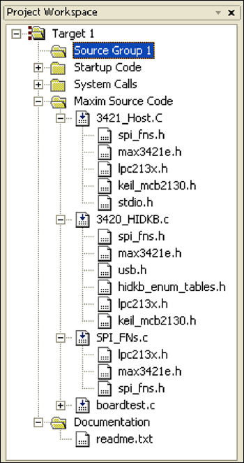
Figure 8. Keil project structure
Figure 8 shows the three main modules and expands to show their file dependencies. The unexpanded modules are internal processing files required by the Keli development environment.
The SPI_FNs.C module contains common functions called by the other two modules.
void init_PLL (void) This function sets the PLL and clock divider of LPC2138. The crystal attached to LPC2138 (FOSC) is 12.000MHz. According to the formula CCLK = FOSC × M, set the CPU frequency to 48MHz, where M = 4. The LPC2138 uses an internal CCO (current controlled oscillator) frequency multiplier FOSC to obtain a higher internal frequency. FCCO = CCLK × 2 × P. FCCO must be between 156MHz and 320MHz. For P = 2, FCCO = 48MHz × 2 × 2 = 192MHz.
Note: The Keil file startup.s also contains the startup code to set the PLL parameters. The init_PLL () function will effectively replace these settings.
Important warning: There are risks associated with modifying these settings. Incorrect settings can force the LPC2138 to exceed its prescribed limits, thus stopping the Keil debugger. If this happens, the remedy is to use the Flash Magic utility software to erase the flash memory of the LPC2138 (use the second serial port and connect to P2 on the Keil board), modify the PLL settings in the code, and then try again.
The init_IO function initializes the LPC2138's I / O pins and SPI unit (SPI and SSP): SPI is controlled by the CCLK / 8 clock and the maximum value is allowed. SCLK is 48MHz / 8 = 6MHz. SSP is controlled by the CCLK / (2 x VBDIV) clock. VBDIV is set to 1, making the SCK signal of the MAX3421E 48MHz / 2 = 24MHz. The SCK input of the MAX3421E can run up to 26MHz. About SPI interface
The SPI interface uses the following signals: MOSI master output data, slave input data MISO master input data, slave output data SCLK serial clock, LPC2138 provides SS # slave selection, LPC2138 drives LPC2138 SPI hardware to control the first three signals, But SS # uses a GP-OUT pin (P0.7) to directly set and clear.
About SSP interface Although SSP has a hardware SS # pin, it is easier to use GP-OUT pin as SS # (P0.20).
Hwreg
Hwritebytes
These functions use the LSP2138's SSP hardware to write registers and FIFO data to the MAX3421E. The H prefix indicates host operation. Hwreg writes a signal register value; Hwritebites writes multiple bytes to the MAX3421E's FIFO.
Hrreg
Hreadbytes
These functions use LPC2138's SSP hardware to read register and FIFO data from the MAX3421E.
SSP interface
SSP hardware needs to be decoded, which requires data FIFOs on the transmit and receive channels. In an SPI operation, every 8-bit data shift out is always accompanied by 8-bit data shift in. The LPC2138 uses the following steps to access the MAX3421E's SPI interface: Trigger SS # (low) to send a command byte consisting of a registration number and a direction bit to send / receive one or more data bytes to release SS # (high) SPI write operation is simple and clear— Each data will be moved out, and the data in the input FIFO can be ignored. But the read operation is more complicated because the read FIFO contains at least one bad byte, which is automatically recorded by the clock control in step 2. Because the previous multi-byte write operation can also make the input data invalid. The input FIFO cannot be disabled or cleared by hardware. Therefore, the code to read the SPI data must first manually clear the FIFO, that is, read the bytes from the SSPDR, until the flag bit that reads the FIFO is not empty is released.
Pwreg
PwregAS
Pwritebytes
These functions use the SPI hardware of the LPC2138 to write registers and FIFO data to the MAX3420E. The second function writes the register value as the first function, but it also sets the ACKSTAT bit in the SPI command byte. This is a shortcut to stop USB control transfer. Please refer to application note 3598, "MAX3420E Programming Guide" for details.
Prreg
PrregAS
Preadbytes
These functions use the SPI hardware of the LPC2138 to read the register and FIFO data from the MAX3420E. The second function reads the register value as the first function, but also sets the ACKSTAT bit in the SPI command.
readoutreadout This function updates the 7-segment information display connected to the MAX3421E general-purpose output pin GPO [6: 0]. The function retains the setting of GPO [7], which controls the USB “A†connector (J1 of the evaluation board) VBUS switch.
The 3421_Host.C module implements the MAX3421E USB host. The host accesses the USB device and reports the enumerated data through the serial port of the MCB22310. For reference, Appendix A shows the LeCroy (CATC) bus process for the host to enumerate the built-in devices implemented by 3420_HIDKB.C.
There are three types of functions in this module: Initialization functions Common functions called in the main function main () The following instructions will follow this order.
Reset_HostMAX3421E contains power-on reset, so this operation is not necessary. Nonetheless, this field is used during the program development phase, and the debugging process can be initialized without repeating power-on, which is a good way to reset the function. Enabling this function clears the device without previous debugging information.
Resetting the MAX3421E stops the on-chip oscillator. After releasing the reset, this function will wait for the OSCOKIRQ bit (oscillator normal interrupt request) to become valid before returning.
The function iniTIalize_3420 is in the 3420_HIDKB.C module.
The iniTIalize_ARM_Interrupts function establishes the ARM vector interrupt as follows: EINT0 is connected to the INT pin of MAX3420E, using priority 0 (highest). TImer0 is used for function luminous body flashing, use priority 1. EINT2 is connected to the INT pin of the MAX3421E, and the specified priority is 2. This interrupt is not used in this program. Of course, this interrupt is provided for convenience. Timer1 is used to detect the send / stop button (used in 3420_HIDKB.C), using priority 3. service_irqs This function is in the 3420_HIDKB.C module. It performs HID keyboard emulation. The code that initializes the ARM interrupt only needs to set the address as an interrupt vector.
A simple method of waitframes for USB host to measure time is to count the number of 1ms frame flags. When the microcontroller sets the register bit SOFKANAB = 1, the MAX3421E automatically generates these frame flags consisting of SOF packets in full-speed mode or "keep-alive" pulses in low-speed mode, and then the FRAMIRQ bit is triggered every millisecond.
USB regulations require certain long delay times, such as resetting a device and giving it a "reset recovery time." Calling the waitframes function will be an easy way to achieve a relatively long delay time.
The detect_device function returns after detecting that a USB device is inserted into the USB-A connector J1.
wait_for_disconnect This function returns after detecting that a device inserted into the USB-A connector is disconnected.
Send_Packet All functions that send USB packets call this function. Figure 9 shows the bus process of the IN transaction and the C program that implements it.
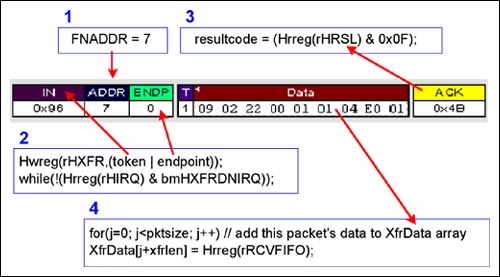
Figure 9. Start USB bus action, C program function is called by MAX3421E
The microcontroller sets the function address in the FNADDR register. Because the load value remains unchanged until the microcontroller reloads the FNADDR register, there is no need to repeat this step for each data packet. The microcontroller begins to transfer data by writing to the HXFR register, indicating the USB token and terminal. Then wait for HXFRDNIRQ (Host Transfer Complete) to trigger IRQ and send the signal to complete. The microcontroller reads the HRSL (host calculation result) register to determine the result of the transaction. The 16 calculation result codes indicate the following results: A. Success (ACK)
B. Equipment occupation (NAK)
C. Abnormal handshake (STALL)
D. Device failure, such as timeout, crosstalk or bus error. The microcontroller reads the count register bytes, then unloads the RCVFIFO and stores the data in a byte array.
This function handles NAK retries and continuously restarts data transmission until: ACK handshake is received, or the preset limit set by the constant NAK_LIMIT is exceeded. If the device does not respond, the function retries the transmission until it is restricted by RETRY_LIMIT.
The CTL_Write_ND function performs control-write operations in the no-data mode (_ND = no data). This function is only called when the host Set_Address requests. It can implement two calls of Sent_Packet: the first one is for SETUP data packet, and the second one is for IN-Handshake data packet.
The IN_Transfer function calls Send_Packet (specified IN) as much as possible to regain the USB data record. The MAX3420E and MAX3421E terminal FIFOS are 64 bytes long. Such a long character description, for example, requires multiple IN request data packets to form a large array (XfrData [2000]).
The CTL_Read function handles the 3-state CONTROL-Read USB transaction and calls three functions: Call Send_Packet to send the SETUP data packet, call IN_Transfer to make the data enter XfrDaTa [], call Send_Packet to send the OUT-Handshake data packet, enumerate_device This function performs 10 shown in Appendix A Data transmission. Because it calls the previous function to implement low-level USB operation, it is easy to understand the enumeration steps by studying this function.
The print_error function checks the 4-bit HRSL value (item 3 in Figure 9) to print out the host's transmission result. If the pass data is 0, no printout. This function returns the HRSL value, so calling this function can easily detect errors, for example: if (print_error (HR)) return; 3420_HIDKB.C This module uses MAX3420E to implement a USB peripheral that conforms to the standard HID class and can be like a standard keyboard Enter text automatically as you type. The entry point is the service_irqs function, which is called as an interrupt service routine when responding to the EINT1 pin of LPC2138. The ENT1 pin is connected to the INT output pin of the MAX3420E.
The Reset_Peripheral function resets the MAX3420E in the same way as Reset_Host.
The initialize_3420 function accomplishes three things: Configure the MAX3420E SPI interface to achieve full-duplex operation (separate the MOSI and MISO pins) Configure the MAX3420E INT pin to be valid on the rising edge Enable the MAX3420E interrupt service_irqs through the application program The device is disconnected. This function also calls do_SETUPC to handle enumeration and do_IN3 to handle keyboard input.
Note: To streamline the code, this application does not handle USB suspend-resume tasks. For an example of this function, please refer to Maxim Application Note 3690, "USB Stick Lifting Program for MAX3420E (and Others)". The enumeration code in AN3690 serves as the basis for 3420_HIDKB.C.
The do_SETUP function handles device enumeration by checking each byte in the 8-byte SETUP data packet, and then calls the function to handle specific requests. The code only handles USB standard request classes, because there is no USB classification or customer request implemented in this application.
The do_IN3 function sends key press information based on the Message [] character array in HIDKB_enum_tables.h. The format of three bytes per character is defined in the same file as HID Report Descriptor, as shown in Figure 10.
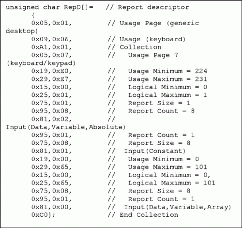
Figure 10. Report Descriptor details the 3-byte data format of a keyboard key
Final consideration and disclaimer The USB device plugged into J1 may be any one of the billion or so available devices, so it goes without saying that there will be various responses to satisfy the host's enumeration request. Any device that passes the compatibility test (with a USB logo display certificate) will be displayed correctly when enumerated. The fault detection in this program is completed by checking the HRSL value after each host transaction. Because many fault conditions are difficult to simulate, fault checking has not been extensively tested.
Appendix A 3240E_HIDKB.C enumerated USB bus tracking process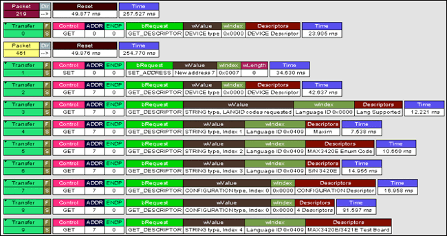
More detailed image (PDF, 234kB)
This application note is application note 3997, "Building a Maxim USB Library". The Keil â„¢ project containing the Maxim demo program can be downloaded.
Introduction The Maxim USB library is a combination of two circuit boards and C language programs. With this system, you can: research, operate, test, and modify USB-enabled devices based on an ARM7 microcontroller (µC) connected to the MAX3420E USB peripheral controller. Research, operation, testing, and modification of a USB function host based on an ARM7 microcontroller (µC) connected to the MAX3421E USB host controller. Figure 1 shows the data retrieval from the USB stick by the host. Use a USB cable to connect the host to the peripherals and run the host and peripherals at the same time. When developing USB host or USB peripheral code, it is useful to have a reference design on the other end of the USB cable. In this way, both ends of the USB cable, the host and the peripherals are executed the same C language code, so it has controllability and customization.

Figure 1. The MAX3421 host / ARM retrieves enumerated data from any USB peripheral and connects to the PC running a terminal emulation program via the serial port to report the results.
Other data programming guides, data sheets, and MAX3420E and MAX3421E application notes provided on the Maxim website:
MAX3420E
MAX3421E
Maxim Application Note AN3937, "Building a Maxim USB Library"
Hardware This application uses C language code to run on two board devices: MAX3421 evaluation (EV) board, the first circuit board Keil MCB2130 board, the second circuit board

Figure 2. The Maxim evaluation board plugs into the Keil MCB2130 board.
Figure 2 shows the board-level equipment. The blue circuit board is Keil MCB2130, which contains an ARM7 chip, Philips® LPC2138. This microcontroller contains 2 SPI ™ hardware units connected to two Maxim USB control chips.
The erected circuit board is MAX3421EEVKIT-1. A MAX3420E peripheral controller is connected to an SPI port of ARM and wired to the USB "B" connector (J5), labeled "3420 P" in Figure 2 (P stands for peripheral). The MAX3421E host / peripheral controller is connected to another ARM SPI port and wired to the “3421P†(J2) and “3421H†(J1) connectors (H stands for host). The code running in the application uses the MAX3421E as a host, so the USB connector (J2) in the middle of the evaluation suite board is not used.
The host software uses one of the two serial ports (P1 on the MCB2130 circuit board) to send the USB description information to the PC running the terminal emulation program. Terminal programs, such as the Tera terminal program, can emulate the terminal (VT100) and identify the special "transfer code" sequence sent by the program to clear the screen and reset the pointer. The serial port of the terminal program is set to 38400, N, 8, 1, without flow control.
The beige square box and ribbon cable in Figure 2 are Keil ULINK JTAG load-debuggers. The Keil µVision®3 development environment supports this debug unit. The MCB2130 comes with an evaluation version of µVision3, a Keil tool set with a fully functional version. But the evaluation version has a 16kB limit on code capacity.
The attachment of this application note contains the source files of the entire Keil project, as well as the loading module in hex format. If there is a ULINK JTAG unit, the code can be compiled and can be loaded and debugged through the JTAG port. This is an excellent way to quickly develop USB, modify work host and / or peripheral code to make it suitable for development purposes. If you do not have ULINK, you can use a free program called Flash Magic to load and run hex files. This program is available from the website. Refer to Maxim application note 3937 for information on how to configure and use the program.

Figure 3. Block diagram of the MAX3421EEVKIT-1 circuit board. The shaded oval is the main software module.
Program Function Figure 3 shows the MAX3421EEVKIT-1 circuit block diagram and the software module of this application note. Both the MAX3420E and MAX3421E use the SPI bus to access their register banks. The LPC2138 contains 2 hardware SPI units: a dedicated SPI port (SPI) and a universal serial interface (SSP, synchronous serial port). The SSP can be programmed to implement a second SPI port. The programming of these ports is different. For example, SSP has 8 transmit and receive FIFOs, while SPI has only 1 read buffer. To be compatible with the MAX3420E and MAX3421E, both SPI interfaces are programmed to work in 8-bit data mode. The software module SPI_FNs.C contains register access functions used by both USB controllers.
The MAX3420E belongs to the SPI unit, so for this chip, the function has a "P" (for example, Prreg and Preg) prefix to indicate the peripheral operation. The MAX3421E belongs to the SSP unit, so its access function has an "H" prefix (such as Hwreg), indicating that it is operated by the host.
The peripheral program C module 3420_HIDKB.C implements a USB peripheral that is connected to a PC by using the connector J5 of the evaluation circuit. The INT output pin of the MAX3420E is connected to the EINT0 (external interrupt 0) pin of ARM7. This interrupt can be triggered at any time when the USB peripheral implemented by the MAX3420E needs to be serviced.
This application lists and implements the standard USD HID (Humanized Interface Device). A major advantage of conforming to the standard Windows® platform is that the device driver is built into Windows, eliminating the need to install a dedicated driver. Windows recognizes the device implemented by this application as a standard keyboard. Pressing any four buttons connected to the MAX3420E GP-IN pin will cause the "keyboard" to enter text strings in any open receive text window, such as notepad and writing pad.
Note: This application can enter text in any text-receiving application, such as e-mail, assembly editor, or Word document. Please make sure there is a safe application before pressing the key, such as notepad is opened and is in a valid state. The author can determine from experience that entering invalid text in an open C source file will not compile completely.
The host code 3241_Host_EVK.C file contains the host code, which enables the MAX3421E to complete certain enumeration steps that are similar to the enumeration steps performed by the PC when a USB device is inserted into connector J4. The main () function in this module is like an interrupt service routine for HID keyboard code. The EINT0 interrupt service routine is as follows: // EINT0 Interrupt handler--MAX3420E INT pin void INT3420 (void) __irq {service_irqs (); // Do the USB thing in 3420_HIDKB_INT_EVK.C module EXTINT = 1; // Clear EINT0 interrupt flag ( b0) VICVectAddr = 0; // Dummy write to indicate end of interrupt service} The basic program main () contains the following infinite loop subroutines:
while (1) {detect_device (); waitframes (200); // Some devices require this enumerate_device (); wait_for_disconnect ();} The Enumerate_device () function completes most of the work, sends a USB request to the connected device, and through the serial port Report the results. Any USB device is plugged into connector J1 of the evaluation board. This function will send an enumeration request to the device and report the result via the serial port (Figure 1).
Synchronous host / peripheral operation Because the MAX3421EEVKIT-1 circuit board contains a USB peripheral and a USB host, and they use a separate SPI interface on the ARM7, the software can be easily written to allow the host and peripheral applications to run simultaneously . The host application runs main () to talk to the MAX3421E in the background, and the HID peripheral code uses the MAX3420E interrupt to activate the service_irqs () function.
If the connectors J5 and J1 of the evaluation board are connected with a USB cable, the ARM processor can act as a USB host to talk to the peripheral, and this peripheral is itself. Figure 4 shows the report of 3421_Host.C's host code querying the peripherals implemented by 3420_HIDKB.C.

Figure 4. Demonstration of the code for asking itself via USB
Host code development reads through the enumerate_device () function to help understand how the USB host works and also to understand how to command the MAX3421E to complete various host operations when enumerating USB devices. While developing the host code, if the response process of inserting the host into the peripheral is unclear, sometimes it will be difficult to diagnose the problem. If you have reference peripherals in all controls (3420_HIDKB.C module), it will make it easy to find the problem and change the response of the device to test the host hardware.
The peripheral code development host is an excellent query tool for developing USB peripheral code. The combination of the MAX3421E and 3421_Host.C modules produces a simple but powerful USB packet generator and analyzer. By writing C language host code, you can control the peripheral status; MAX3421E displays the peripheral's response process.
The example assumes writing peripheral code to handle USB strings. Write the manufacturer string XYZ Widget Company in the hidkb_enum_tables.h file as follows: // STRING descriptor 1--Manufacturer ID {18, // bLength 0x03, // bDescriptorType = string 'X', 'Y', 'Z ',' ',' W ',' i ',' d ',' g ',' e ',' t ',' ',' C ',' o ',' m ',' p ',' a ',' n ',' y '}, compile the file, load it into ARM's flash memory and run it. The host program will report the following manufacturer string:

Figure 5. Undesirable result, the routine does not display the manufacturer's name as required, and the code is defective.
What's wrong? It turned out that USB stipulates that text strings are expressed in Unicode, that is, each character is expressed in two bytes. Review the source code of the peripheral, and change as follows: // STRING descriptor 1--Manufacturer ID {35 // bLength 0x03, // bDescriptorType = string 'X', 0, 'Y', 0, 'Z', 0, ' ', 0,' W ', 0,' i ', 0,' d ', 0,' g ', 0,' e ', 0,' t ', 0,' ', 0,' C ', 0 , 'o', 0, 'm', 0, 'p', 0, 'a', 0, 'n', 0, 'y' // Unicode!}, compile and run, you should see:

Figure 6. Normal code routine, using Unicode format, you can see the results.
The result has improved, but it is not perfect. Where is the "y" in the company? Carefully count that the string has 35 characters and enter it as the first byte to display the string length. What the design does not pay attention to is that the length byte is also a string, and must contain the first two bytes. The final modification of the code is as follows: // STRING descriptor 1--Manufacturer ID {37 // bLength 0x03, // bDescriptorType = string 'X', 0, 'Y', 0, 'Z', 0, '', 0, 'W', 0, 'i', 0, 'd', 0, 'g', 0, 'e', ​​0, 't', 0, '', 0, 'C', 0, 'o' , 0, 'm', 0, 'p', 0, 'a', 0, 'n', 0, 'y' // Unicode!}, This is what the result should look like:

Figure 7. The best code example. The code can now implement what the design wants to achieve.
Through testing the peripheral code and using the host controller and encoding operation / analysis, the reported result is the actual USB message sent from the MAX3420E to the MAX3421E, so you can see the exact same result as the PC response. The best thing is that these can be implemented on a controllable basis, so there is no need to worry about how the PC responds to make code development errors.
Code description

Figure 8. Keil project structure
Figure 8 shows the three main modules and expands to show their file dependencies. The unexpanded modules are internal processing files required by the Keli development environment.
The SPI_FNs.C module contains common functions called by the other two modules.
void init_PLL (void) This function sets the PLL and clock divider of LPC2138. The crystal attached to LPC2138 (FOSC) is 12.000MHz. According to the formula CCLK = FOSC × M, set the CPU frequency to 48MHz, where M = 4. The LPC2138 uses an internal CCO (current controlled oscillator) frequency multiplier FOSC to obtain a higher internal frequency. FCCO = CCLK × 2 × P. FCCO must be between 156MHz and 320MHz. For P = 2, FCCO = 48MHz × 2 × 2 = 192MHz.
Note: The Keil file startup.s also contains the startup code to set the PLL parameters. The init_PLL () function will effectively replace these settings.
Important warning: There are risks associated with modifying these settings. Incorrect settings can force the LPC2138 to exceed its prescribed limits, thus stopping the Keil debugger. If this happens, the remedy is to use the Flash Magic utility software to erase the flash memory of the LPC2138 (use the second serial port and connect to P2 on the Keil board), modify the PLL settings in the code, and then try again.
The init_IO function initializes the LPC2138's I / O pins and SPI unit (SPI and SSP): SPI is controlled by the CCLK / 8 clock and the maximum value is allowed. SCLK is 48MHz / 8 = 6MHz. SSP is controlled by the CCLK / (2 x VBDIV) clock. VBDIV is set to 1, making the SCK signal of the MAX3421E 48MHz / 2 = 24MHz. The SCK input of the MAX3421E can run up to 26MHz. About SPI interface
The SPI interface uses the following signals: MOSI master output data, slave input data MISO master input data, slave output data SCLK serial clock, LPC2138 provides SS # slave selection, LPC2138 drives LPC2138 SPI hardware to control the first three signals, But SS # uses a GP-OUT pin (P0.7) to directly set and clear.
About SSP interface Although SSP has a hardware SS # pin, it is easier to use GP-OUT pin as SS # (P0.20).
Hwreg
Hwritebytes
These functions use the LSP2138's SSP hardware to write registers and FIFO data to the MAX3421E. The H prefix indicates host operation. Hwreg writes a signal register value; Hwritebites writes multiple bytes to the MAX3421E's FIFO.
Hrreg
Hreadbytes
These functions use LPC2138's SSP hardware to read register and FIFO data from the MAX3421E.
SSP interface
SSP hardware needs to be decoded, which requires data FIFOs on the transmit and receive channels. In an SPI operation, every 8-bit data shift out is always accompanied by 8-bit data shift in. The LPC2138 uses the following steps to access the MAX3421E's SPI interface: Trigger SS # (low) to send a command byte consisting of a registration number and a direction bit to send / receive one or more data bytes to release SS # (high) SPI write operation is simple and clear— Each data will be moved out, and the data in the input FIFO can be ignored. But the read operation is more complicated because the read FIFO contains at least one bad byte, which is automatically recorded by the clock control in step 2. Because the previous multi-byte write operation can also make the input data invalid. The input FIFO cannot be disabled or cleared by hardware. Therefore, the code to read the SPI data must first manually clear the FIFO, that is, read the bytes from the SSPDR, until the flag bit that reads the FIFO is not empty is released.
Pwreg
PwregAS
Pwritebytes
These functions use the SPI hardware of the LPC2138 to write registers and FIFO data to the MAX3420E. The second function writes the register value as the first function, but it also sets the ACKSTAT bit in the SPI command byte. This is a shortcut to stop USB control transfer. Please refer to application note 3598, "MAX3420E Programming Guide" for details.
Prreg
PrregAS
Preadbytes
These functions use the SPI hardware of the LPC2138 to read the register and FIFO data from the MAX3420E. The second function reads the register value as the first function, but also sets the ACKSTAT bit in the SPI command.
readoutreadout This function updates the 7-segment information display connected to the MAX3421E general-purpose output pin GPO [6: 0]. The function retains the setting of GPO [7], which controls the USB “A†connector (J1 of the evaluation board) VBUS switch.
The 3421_Host.C module implements the MAX3421E USB host. The host accesses the USB device and reports the enumerated data through the serial port of the MCB22310. For reference, Appendix A shows the LeCroy (CATC) bus process for the host to enumerate the built-in devices implemented by 3420_HIDKB.C.
There are three types of functions in this module: Initialization functions Common functions called in the main function main () The following instructions will follow this order.
Reset_HostMAX3421E contains power-on reset, so this operation is not necessary. Nonetheless, this field is used during the program development phase, and the debugging process can be initialized without repeating power-on, which is a good way to reset the function. Enabling this function clears the device without previous debugging information.
Resetting the MAX3421E stops the on-chip oscillator. After releasing the reset, this function will wait for the OSCOKIRQ bit (oscillator normal interrupt request) to become valid before returning.
The function iniTIalize_3420 is in the 3420_HIDKB.C module.
The iniTIalize_ARM_Interrupts function establishes the ARM vector interrupt as follows: EINT0 is connected to the INT pin of MAX3420E, using priority 0 (highest). TImer0 is used for function luminous body flashing, use priority 1. EINT2 is connected to the INT pin of the MAX3421E, and the specified priority is 2. This interrupt is not used in this program. Of course, this interrupt is provided for convenience. Timer1 is used to detect the send / stop button (used in 3420_HIDKB.C), using priority 3. service_irqs This function is in the 3420_HIDKB.C module. It performs HID keyboard emulation. The code that initializes the ARM interrupt only needs to set the address as an interrupt vector.
A simple method of waitframes for USB host to measure time is to count the number of 1ms frame flags. When the microcontroller sets the register bit SOFKANAB = 1, the MAX3421E automatically generates these frame flags consisting of SOF packets in full-speed mode or "keep-alive" pulses in low-speed mode, and then the FRAMIRQ bit is triggered every millisecond.
USB regulations require certain long delay times, such as resetting a device and giving it a "reset recovery time." Calling the waitframes function will be an easy way to achieve a relatively long delay time.
The detect_device function returns after detecting that a USB device is inserted into the USB-A connector J1.
wait_for_disconnect This function returns after detecting that a device inserted into the USB-A connector is disconnected.
Send_Packet All functions that send USB packets call this function. Figure 9 shows the bus process of the IN transaction and the C program that implements it.

Figure 9. Start USB bus action, C program function is called by MAX3421E
The microcontroller sets the function address in the FNADDR register. Because the load value remains unchanged until the microcontroller reloads the FNADDR register, there is no need to repeat this step for each data packet. The microcontroller begins to transfer data by writing to the HXFR register, indicating the USB token and terminal. Then wait for HXFRDNIRQ (Host Transfer Complete) to trigger IRQ and send the signal to complete. The microcontroller reads the HRSL (host calculation result) register to determine the result of the transaction. The 16 calculation result codes indicate the following results: A. Success (ACK)
B. Equipment occupation (NAK)
C. Abnormal handshake (STALL)
D. Device failure, such as timeout, crosstalk or bus error. The microcontroller reads the count register bytes, then unloads the RCVFIFO and stores the data in a byte array.
This function handles NAK retries and continuously restarts data transmission until: ACK handshake is received, or the preset limit set by the constant NAK_LIMIT is exceeded. If the device does not respond, the function retries the transmission until it is restricted by RETRY_LIMIT.
The CTL_Write_ND function performs control-write operations in the no-data mode (_ND = no data). This function is only called when the host Set_Address requests. It can implement two calls of Sent_Packet: the first one is for SETUP data packet, and the second one is for IN-Handshake data packet.
The IN_Transfer function calls Send_Packet (specified IN) as much as possible to regain the USB data record. The MAX3420E and MAX3421E terminal FIFOS are 64 bytes long. Such a long character description, for example, requires multiple IN request data packets to form a large array (XfrData [2000]).
The CTL_Read function handles the 3-state CONTROL-Read USB transaction and calls three functions: Call Send_Packet to send the SETUP data packet, call IN_Transfer to make the data enter XfrDaTa [], call Send_Packet to send the OUT-Handshake data packet, enumerate_device This function performs 10 shown in Appendix A Data transmission. Because it calls the previous function to implement low-level USB operation, it is easy to understand the enumeration steps by studying this function.
The print_error function checks the 4-bit HRSL value (item 3 in Figure 9) to print out the host's transmission result. If the pass data is 0, no printout. This function returns the HRSL value, so calling this function can easily detect errors, for example: if (print_error (HR)) return; 3420_HIDKB.C This module uses MAX3420E to implement a USB peripheral that conforms to the standard HID class and can be like a standard keyboard Enter text automatically as you type. The entry point is the service_irqs function, which is called as an interrupt service routine when responding to the EINT1 pin of LPC2138. The ENT1 pin is connected to the INT output pin of the MAX3420E.
The Reset_Peripheral function resets the MAX3420E in the same way as Reset_Host.
The initialize_3420 function accomplishes three things: Configure the MAX3420E SPI interface to achieve full-duplex operation (separate the MOSI and MISO pins) Configure the MAX3420E INT pin to be valid on the rising edge Enable the MAX3420E interrupt service_irqs through the application program The device is disconnected. This function also calls do_SETUPC to handle enumeration and do_IN3 to handle keyboard input.
Note: To streamline the code, this application does not handle USB suspend-resume tasks. For an example of this function, please refer to Maxim Application Note 3690, "USB Stick Lifting Program for MAX3420E (and Others)". The enumeration code in AN3690 serves as the basis for 3420_HIDKB.C.
The do_SETUP function handles device enumeration by checking each byte in the 8-byte SETUP data packet, and then calls the function to handle specific requests. The code only handles USB standard request classes, because there is no USB classification or customer request implemented in this application.
The do_IN3 function sends key press information based on the Message [] character array in HIDKB_enum_tables.h. The format of three bytes per character is defined in the same file as HID Report Descriptor, as shown in Figure 10.

Figure 10. Report Descriptor details the 3-byte data format of a keyboard key
Final consideration and disclaimer The USB device plugged into J1 may be any one of the billion or so available devices, so it goes without saying that there will be various responses to satisfy the host's enumeration request. Any device that passes the compatibility test (with a USB logo display certificate) will be displayed correctly when enumerated. The fault detection in this program is completed by checking the HRSL value after each host transaction. Because many fault conditions are difficult to simulate, fault checking has not been extensively tested.
Appendix A 3240E_HIDKB.C enumerated USB bus tracking process

More detailed image (PDF, 234kB)
Ethernet Switch,Internet Switches,Ethernet Splitter,Gigabit Managed Ethernet Switch
Chinasky Electronics Co., Ltd. , https://www.chinaskyswitches.com