Hearing loss in up to 30% of adults may be due to the effects of noise. One of the major effects of hearing loss is the inability to selectively hear content in a noisy background. Noise-cancelling headphones can help save our hearing and allow us to enjoy clearer calls, quieter and more peaceful flights and a higher overall standard of living.
“Passive†noise reduction uses earplugs or earmuffs made of plastic, foam, silicone rubber or other materials to mechanically isolate the ear from the environment. Depending on the materials used, passive noise reduction can only affect sounds above 500 Hz. Active Noise Reduction (ANC) technology is effective for frequencies as low as 20 Hz and as high as several thousand Hz. The “active†noise reduction solution fills the gap that is not possible with standard passive noise reduction solutions.
Active noise reduction uses the sound produced by the speakers to reduce other sounds that are transmitted to the ear. There are two options for detecting unwanted sounds: expose the microphone to noise and isolate it from the speaker, or place the microphone as close as possible to the speaker (Figure 1).
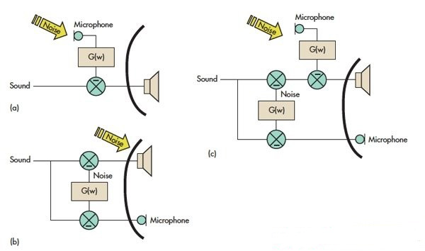
Figure 1: In the design of the feedforward noise canceling headphones (a), the microphone is isolated from the speaker. In the feedback design (b), the microphone is placed close to the speaker. Feedforward and feedback methods can be combined to be applied to the same headset (c).
With the feedforward method, if the sound isolation between the speaker and the feedforward microphone is good enough, the playback path will not be affected. This is a big advantage when the noise reduction function is turned off or the battery is running out and the headphones are operating in passive mode. The music playback effect is still good. The feedforward topology also makes it easy to create a “hearing aid†mode that magnifies the instant sound environment without having to remove the headphones and listen to people.
Feedforward Design <br> With a feedforward topology, designers can perform acoustic analysis of the headphones to determine how the noise changes in frequency, phase, and amplitude as it reaches the ear. The transfer function G(w) model can then be electrically established and inserted between the microphone and the speaker.
Feedforward designs are often affected by directional problems, so the microphone must be omnidirectional. Also, noise channels cannot be mechanically concentrated. Because the microphone must acquire these noises before the noise reaches the ear, the parallel sound path must be minimized.
Feedback Design <br> The feedback topology works according to the actual noise on the ear, which by definition is more accurate than the analog effect used by the feedforward structure. However, the responsiveness of the system constrains performance. Special care must be taken when defining the transfer function to avoid introducing instability, such as positive feedback.
The feedback design deducts the playback of the microphone. The resulting signal represents the noise around the ear. Use the transfer function to eliminate unwanted sounds with signals with phase shifts.
An ideal headset for feedback active noise reduction will achieve zero delay between the speaker and the microphone that gets the speaker output. This is not possible because in this case, the speaker and microphone will need to share the same acoustic center. This will not be possible physically. What you can do is place the microphone as close as possible to the speaker film to reduce propagation delay.
Since the microphone cannot distinguish between noise and playback in a feedback headset, headphones with a feedback design usually have some signal distortion. To overcome this problem, a common method is to add an equalization circuit to the playback path to ensure that the sound is the same whether active noise reduction is activated or not.
Feedforward and feedback can also be combined in the same headset. This can take advantage of each of the two approaches, but it also increases the complexity of the design and the additional cost (requiring trade-offs).
Practical Design Considerations The biggest challenge of a feedforward solution is to ensure that the environment around the user's ear is controlled. Since the shape and size of the user's ear vary from person to person, the suitability of the earphone may vary. If you want to achieve the best noise reduction, you need different transfer functions to match these different physical characteristics.
This means that when earphones are designed in a feedforward manner, the headphones must be suitable for each person or must be designed to ensure that the differences between different people have the least impact on the transfer function. A controlled leakage path in the feedforward headset can meet this need.
When considering a feedback design, the main issue is where to place the microphone and how to ensure that the acoustic properties are controlled over the entire frequency range. This is very subtle, but it is not an unknown area. Many patents involve research on microphone position and front/rear cavity size/ratio.
In the trade-off of the design scheme, the audio response is usually prioritized, and the active noise reduction performance can be very well matched. In these cases, active noise reduction characteristics are typically limited by the frequency bandwidth, but can achieve sufficient or even significant levels of noise reduction. This method ensures the sound quality of the headphones even when the power is exhausted.
Another approach is to prioritize active noise reduction, where the audio response must be adjusted to ensure sound. In this way, the headset needs to remain powered, or some kind of internal passive equalization must be used to produce a "pleasing" sound.
Analog Pairs <br> Designers can choose between digital or analog signal processing methods. Traditional digital solutions rely primarily on predictions and can only achieve noise reduction for "steady state" noise, such as constant engine noise or other constant frequency noise.
Active noise canceling headphones must minimize delays to cope with uneven noise. The distance between the microphone and the speaker is typically 0.7 cm, which is equivalent to a 20 μs sound propagation delay. For digital implementations, analog-to-digital conversion, signal processing, and digital-to-analog conversion are also only 20μs apart (Figure 2).
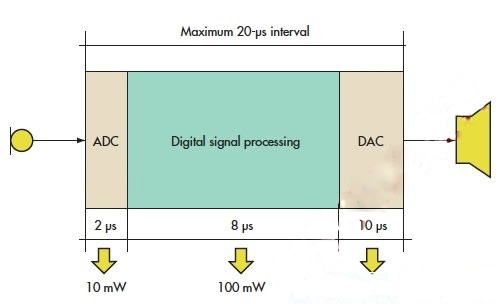
Figure 2: The signal chain propagation delay does not exceed 20μs with a microphone-to-speaker distance of 0.7cm.
The typical power consumption of a standard 150MIPS, 24-bit DSP, analog-to-digital converter (ADC), and digital-to-analog converter (DAC) that meets timing requirements is approximately 113mW. In contrast, simulations with similar (if not better) performance Applications such as the Austrian Microelectronics (AMS) AS3400 consume less than 10mW of power. Due to battery life, the industry generally prefers to use analog solutions.
On the other hand, the development of digital solutions has become more precise and software oriented. Moreover, designers can more easily achieve features such as equalization, bass boost and surround sound - of course, this will come at the expense of extra calculations and more power consumption.
While analog solutions rely more on experience and rely on a large amount of existing electroacoustic engineering expertise, this will give designers who can apply expertise another important advantage over battery life, size and cost: Respond immediately.
Level of noise reduction <br> Above 1 or 2 kHz, each earphone can exhibit some form of passive noise reduction because the insulation blocks the environment
Noise enters the ear. Similarly, 20 to 30 dB of noise isolation is usually higher than several kilohertz. The good noise-cancelling headphones have passive noise filtering function, which can filter noise to very low frequency and achieve 5~30dB noise isolation. Even without power, the headphones bring peace and quiet.
However, good passive noise reduction also has its drawbacks: a phenomenon known as occlusion. The best example is to put your fingers in your ears and talk. As the sound passes through the bone structure of the chin and nose, the experiencer will hear his voice dull and distorted.
This phenomenon usually makes the user's voice (or even yelling) during the conversation, which is neither prudent nor unpleasant. In addition to removing headphones or earbuds during conversations, you can also use techniques such as sidetones—the sound is captured by a separate microphone and played back with a slight attenuation.
An unexpected advantage of active noise reduction is that it can replace the need for high passive filtering at lower frequencies, such as voice bands. Since the user can turn the active noise reduction function on or off by controlling the switch, this will bring great convenience when the adjacent seat on the aircraft passes the service vehicle and hopes that it can stop the flight attendant.
The feedforward scheme has an optimal point: a narrow band that maximizes noise reduction performance (Figure 3a). In addition, the feedforward scheme enables noise reduction in a wide spectrum, typically up to 4 or 5 kHz.
Feedback active noise reduction tends to be more uniform over its frequency band (Figure 3b). However, the frequency band under consideration is typically limited to about 1 kHz. This limitation depends on the need for stability to ensure that different person or different headphone pressures do not cause sufficient transfer function to change to positive feedback causing oscillation. Noise reduction up to 20dB and 1kHz bandwidth is very common for feedback designs.
The hybrid design combines the advantages of both topologies while minimizing their shortcomings (Figure 3c).
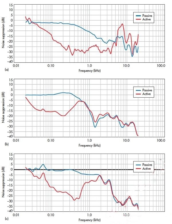
Figure 3: Analog design is a better choice considering battery life, but power consumption is only one factor in design trade-offs.
Design Cases <br> During the product concept phase, OEM engineers must judge all trade-offs and determine whether the product will use feedforward, feedback or hybrid active noise reduction solutions, as well as materials needed for mechanical design.
The next step is to define the shape, size, and headphone and fit. Active noise reduction device vendors can advise on the location of the microphone, vents, and other features associated with the acoustic structure of the headset. The active noise reduction chip integrates all the main functions and provides the necessary performance. Austrian Microelectronics' AS34x0 has everything needed for feedforward design (Figure 4).
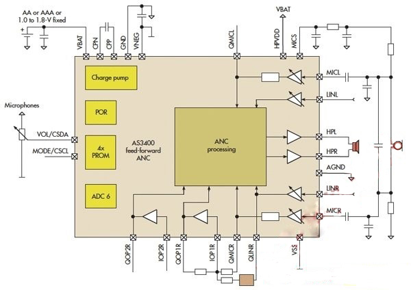
Figure 4: The feedforward scheme (a) typically has a narrow frequency band where noise reduction performance can be maximized. An optimum point of over 25 dB and a bandwidth of up to 4 kHz are very common.
The feedback active noise reduction (b) is flatter. The hybrid design (c) combines the advantages of both designs.
In the next prototype design phase, headset developers turn 3D models into electro-acoustic solutions. At this stage, OEM engineers have made reasonable modifications to the headphone sound. At the same time, chip vendors can use the simulation tools and development kits to participate in the development of the first active noise reduction filter circuit.
The output of this stage is a full-featured headset. The first prototype exhibits the best active noise reduction performance and includes a separate frequency response diagram. Most vendors offer comprehensive circuit reference schematics and further improvements to the mechanical design of the headset to improve active noise reduction. This prototype phase is usually completed after 1 or 2 iterations.
The final step is to integrate these approved modifications and design and layout the printed circuit board (PCB). Once the production confirmation sample is completed, the active noise reduction transfer function can be fine-tuned.
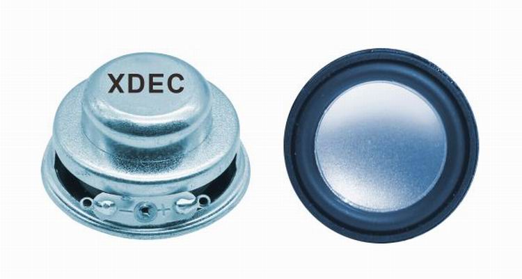
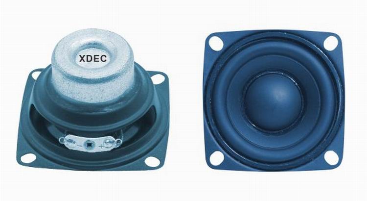
Mini speaker is a kind of speaker unit which is used for multimedia devices. Multimedia Speakers have loud sound, wide frequency response range and rich bass.
Our main multimedia speakers are full ranges speakers units:
1) From the diameter: we have speakers in 1" ~ 3".
2) From the power output, we have speakers of 2W ~ 15W.
FAQ
Q1. What is the MOQ?
XDEC: 2000pcs for one model.
Q2. What is the delivery lead time?
XDEC: 20 days for normal orders, 15 days for urgent orders.
Q3. What are the payment methods?
XDEC: T/T, PayPal, Western Union, Money Gram.
Q4. Can you offer samples for testing?
XDEC: Yes, we offer free samples.
Q5. How soon can you send samples?
XDEC: We can send samples in 3-5 days.
Mini Speaker
Portable Mini Speaker,Bluetooth Mini Speaker,Waterproof Mini Speaker, Mini Lamp Speaker
Shenzhen Xuanda Electronics Co., Ltd. , https://www.xdecspeaker.com