PID control is one of the earliest developed control strategies. It has the advantages of simple algorithm, easy implementation, good robustness and high reliability. It is the most common control method and has been well received in various power control systems. application. For the determination of the PID parameters, the experienced technicians will directly set the PID parameters of the control system according to the previous debugging experience, and finally meet the requirements through continuous debugging. The majority of inexperienced people choose to use the simulation method to pre-test a more appropriate PID parameter, and then continuously debug on this basis. Both methods lack a certain theoretical basis, the workload is relatively large, and in the case of system parameters changes, the impact of the selected PID parameters on system performance is unknown.
Although the mathematical model of complex and nonlinear systems is difficult to determine, on the basis of previous work, after some analysis and simplification, it can be expressed as a form of transfer function. In this paper, PID control is applied to the PWM power system. The transfer function of the system can be completely determined by the zero point, pole and gain factor. The meaning of zero and pole is that when the complex frequency takes a value at zero or pole, the transfer function takes a value of zero or tends to infinity. Therefore, the pole-zero is inevitably closely related to the frequency response. Therefore, the desired response can be achieved by the method of zero-pole coordination configuration.
1 PWM inverter power supply main circuit structure and mathematical model
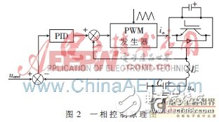
Figure 1 shows the schematic diagram of the main circuit of a three-phase PWM inverter [1]. Vdc is the DC side power supply, two capacitors C2 and C3 provide the ground for the load, and Rs is the equivalent resistance of the IGBT switch. R1 and L are The equivalent resistance and inductance of the output filter inductor, C is the filter capacitor, and ik0 is the load current. In the one-phase loop shown by the thick line in Fig. 1, the modulation wave of one phase is generated by PID adjustment as shown in Fig. 2, and then the PWM signal is generated by comparison with the triangular carrier. Since the three-phase control method is the same, only one-phase circuit is analyzed.
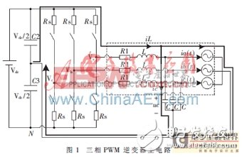
In the main circuit, the power switch tube operates in the "on" and "off" states. The midpoint output voltage Vdc of the bridge arm is a pulse voltage with a magnitude of Vdc/2, and Vk(k=a, b, c) is not continuously. In engineering applications, the state space averaging method is usually used to select the capacitor voltage uc and the inductor current iL as the state variables. The midpoint voltage vk (k=a, b, c) of the bridge arm is used as the input, and the average value vk is used instead. The load current ik0 (k=a, b, c) as the disturbance input, the equation of state for the continuous system of the inverter is:
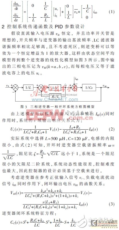
It can be seen from equation (4) that the instantaneous voltage PID closed-loop control system is a high-order system. In the practice of control engineering, it is considered that the control system must have a high response speed and a certain degree of damping. It also requires reducing the influence of nonlinear factors such as dead zone and friction on the system performance, often in the case of high-order systems. The gain is adjusted to give the system a pair of closed-loop common 扼 dominant poles. At this time, the dynamic performance of the second-order system can be used to estimate the dynamic performance of the high-order system.
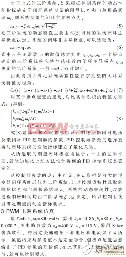
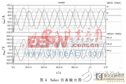
Through a series of derivation and research, the theoretical value of the PID parameters of the three-phase PWM inverter power supply control system is given. The simulation verifies the validity of the parameter. The research has strong engineering application value for the design of three-phase PWM inverter power supply control system.
Data Acquisition Adcs Dacs,Ics Data Acquisition Adcs/Dacs,Data Acquisition Adc / Dac Professional,Ic Chip Data Acquisition Adcs/Dacs
Shenzhen Kaixuanye Technology Co., Ltd. , https://www.iconlinekxys.com