Sensor DC two-wire DC

Sensor DC two-line schematic
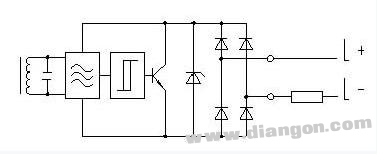
1, wiring voltage: 10-30VDC (10-65VDC)
2, normally open contact (NO) or normally closed contact
3, regardless of NPN and PNP
4, with short circuit protection
5, leakage current is less than or equal to 0.5mA
6, the voltage drop is less than 5V
7, two-wire DC sensor can not be connected in series or parallel connection sensor DC three-wire wiring diagram

Sensor DC three-wire schematic
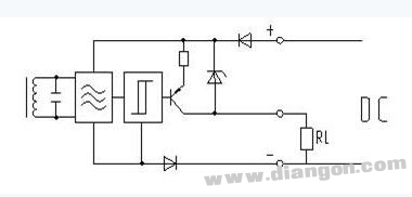
1, wiring voltage: 10-30VDC (10-65VDC)
2, normally open contact (NO) or normally closed contact
3, the voltage drop is less than 1.8V
4, with short circuit protection and polarity protection When the three or four line sensors are connected in series, the voltage drop is added, and the single sensor preparation delay time is added.
Sensor DC four-wire wiring diagram
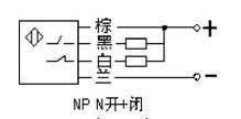

Sensor DC four-wire schematic
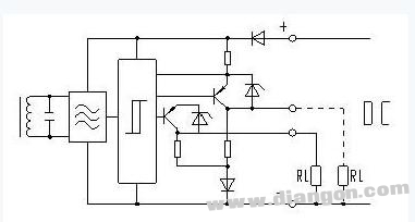
1, wiring voltage: 10-30VDC (10-65VDC)
2, switch between normally open contacts and normally closed contacts
3, with short circuit protection and polarity protection
4, the voltage drop is less than 1.8V
Sensor DC three- or four-wire parallel
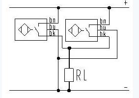
Sensor AC two-wire wiring diagram

1, wiring voltage: 20-250VAC
2, normally open contact or normally closed contact
3. Leakage current is less than or equal to 1.3mA
4, the voltage drop is less than 6.5V
Sensor AC two-wire series connection diagram
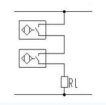
1, normally open contacts: "and" logic
2, normally closed contacts: "or not" logic
3. When connected in series, the voltage drop across the sensor is added, which subtracts the voltage available on the load and therefore cannot be lower than the minimum operating voltage of the load. Please pay attention to the voltage fluctuations of the grid.
Mechanical switch and AC sensor in series

When the sensor is disconnected from the contact, the supply voltage is disconnected. If the mechanical contact is closed during sensor decay, the sensor may become dysfunctional for a short period of time. The sensor preparation delay time is less than or equal to 80ms, and a fault occurs during this time, or it fails.
Compensation method: a resistor is connected in parallel on the mechanical contact. The resistance in parallel makes the power supply of the sensor not interrupted on the mechanical contact. The mechanical contact will not be out of the rotor delay state even if it is opened and closed. .
For 200VAC, the resistance of the resistor is approximately 82KΩ/1W. The approximate calculation method is 400Ω/V.
Sensor AC two-wire parallel
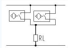
1. Normally open contact: "AND" logic normally closed contact: "NOR" logic
2. When the sensor normally open contact is closed, another parallel sensor is short-circuited. When the sensor is disconnected, a prepared delay time (≤80ms) is required.
Compensation method: A resistor in series with the contact ensures the minimum operating voltage of the sensor and avoids the preparation time after the contact is disconnected. Resistance calculation method: R=10/IP=I square×R
Antenk's High Definition Multimedia Interface (HDMI) connectors and cable assemblies are a series of products that provide an uncompressed digital link between video and audio in a single digital interface connection. Typically they are used with digital versatile (DVD) players, digital television (DVI), set top boxes and other audiovidual devices to consolidate interfaces and eliminate multiple cable assemblies. Adam Tech's HDMI series are small, easy to to use interconnects that can carry up to 5 Gbps of combined video and audio in a single connector/cable.
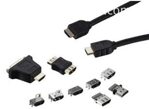
HDMI Connector Overview
High Definition Multimedia Interface (HDMI) connector and cable assemblies deliver the highest quality, high-definition content by providing an uncompressed digital connection from any audio/video source to an audio and/or video monitor over a single cable. The single interface of the Antenk HDMI connector makes it economical and easy to use as it combines both video and multi-channel audio into a single-port connection, eliminating the cost, complexity, and confusion of multiple cables used in A/V systems.
Micro HDMI connectors offer all the advantages of the HDMI standard 1.4 specification and are half the size of the industry Mini HDMI connector. Antenk`s Micro HDMI features a miniature footprint and low-profile height, which offers significant space savings, delivering equivalent mechanical strength and electrical characteristics.
Micro HDMI cable assemblies feature a stylish and compact overmold design and are available in a variety of customizable cable lengths.
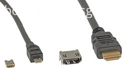
HDMI Connector Types
Standard HDMI (HDMI Type A)
Extended Pin HDMI (HDMI Type B)
Mini HDMI (HDMI Type C)
Micro HDMI (HDMI Type D)
HDMI Connector Features and Benefits
Compact and user-friendly design
Meets consumer equipment needs
Triad signal layout
Low impedance mismatch
Satisfy HDMI 1.4 Specification mechanical and electrical requirements
Customers enjoy all features and benefits of the HDMI 1.4 Specification
Friction lock on receptacle shell
Offers excellent retention force and tactile feel when mating
5 Gbps
Carries uncompressed audio and video in a single cable
Fully shielded connector
EMI/RFI protection
5,000 mating cycles for receptacles
Meets durability requirements for mobile applications
HDMI Connector Applications
Automotive
GPS
Commercial Vehicle
GPS
Consumer
DVD Players/Recorders
Digital camera
LCD and TV panel
Satellite Boxes
Televisions
Video / DVD products
Video games
Smart Phones and Mobile Devices
Smartphones
Hdmi Connectors,Hdmi Type Connector,Mini Hdmi Connector,Micro HDMI Connectors,Card Edge Hdmi Connector,HDMI Connector,Mini HDMI Connector,Micro HDMI Connector
ShenZhen Antenk Electronics Co,Ltd , https://www.atkconnectors.com