The expansion socket is where the shield is installed. The shield allows the I/O board to work like a small motherboard, providing mechanical and electrical connections to other circuits. There are a variety of shields in the room, giving Arduino incredible expansion capabilities.
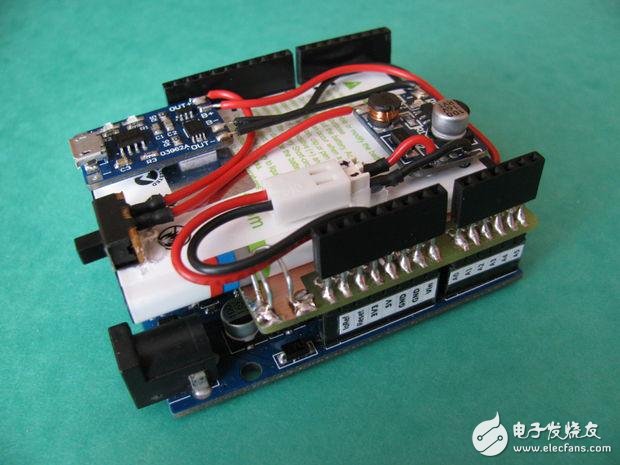
"Scotty, we need more power!".
Here's a tutorial on making a battery protection shield for Arduino.
Step 1: Material
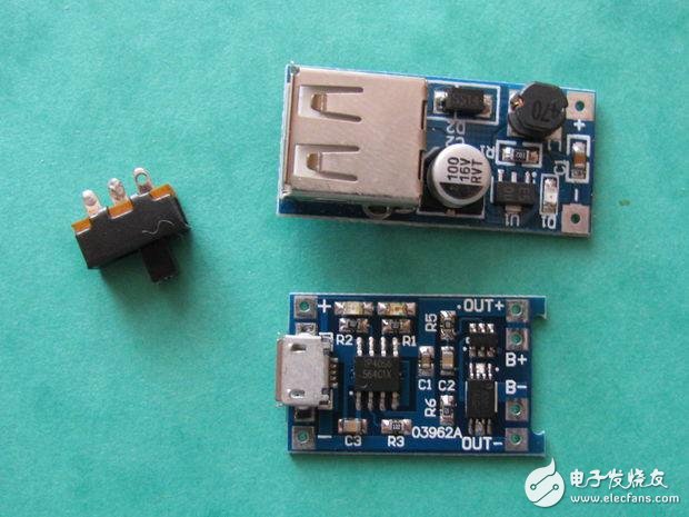
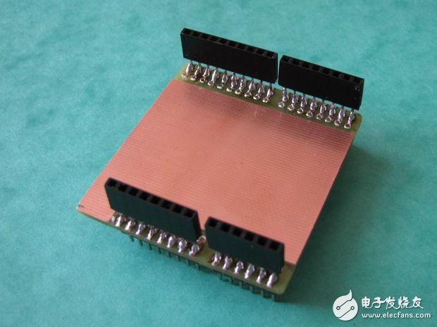
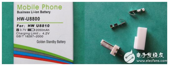
Bill of materials:
· Tablet lithium battery (such as taken from the old phone) (Huawei battery Ideos X5 U8800 can be considered)
· With TP4056 lithium ion charging module
· DC-DC boost module, V_OUT=5 V
· Arduino prototype shield is equivalent
· Red and black wires (I use AWG24)
· double-sided tape
· Metal paper clips
· Some types of lock connectors (I use PSH02-02PG)
Step 2: Module with TP4056 Li-Ion Charger Module (TP4056 is a complete single-cell Li-Ion battery with constant current/constant voltage linear charger. SOP8/MSOP8 package with heatsink on the bottom and fewer external components Making the TP4056 ideal for portable applications. The TP4056 is suitable for USB power and adapter power supplies.)
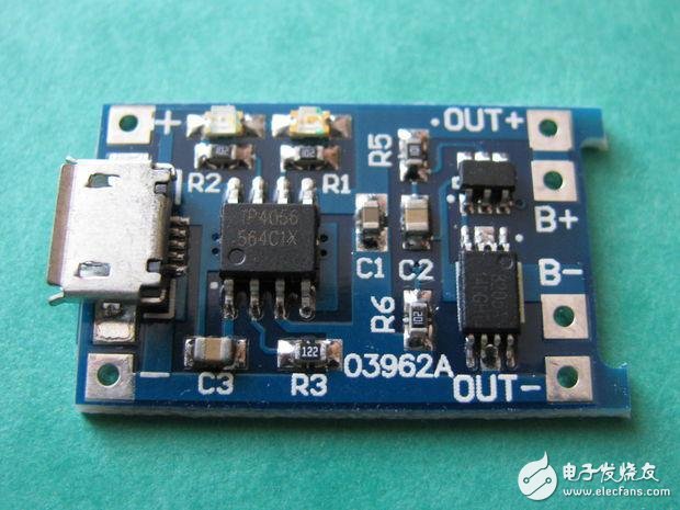
See the picture above. This module consists of two parts: the charger (IC TP4056) and protection to protect the battery from overcharging, overdischarge and short circuit. Excessive charging or short circuit may cause an explosion.
Make sure that you connect the battery to the "B+" and the battery is reduced to "B-", because the wrong polarity will damage the protection circuit, set the maximum charging current resistance R3, R3 → maximum charging current; 1.2 k? → 1000 mA (default); 2 k? → 580 mA; 3 k? → 400 mA.
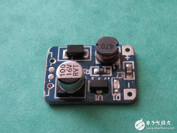
DC-DC boost module, classic boost converter. The output voltage is constant 5 v . See Wikipedia's article on improving converters for more details. Some versions are designed for small DIY powerbanks USB connectors. But the desoldered connector is redundant and unpleasant to work, so you should buy a version without a USB connector.
The third step: connection and welding
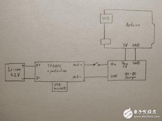
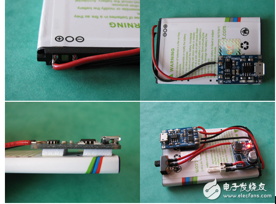
The wiring is based on the diagram above. This should not be difficult. As written above, make sure the battery is connected to "B+" and the battery is reduced to "B-". Do not heat the module and battery with heat because they can be heated to a high temperature to melt the hot melt. Use double-sided tape instead of hot glue. The switch and connector can be attached with hot melt adhesive (as usual).
Step 4: Protect the shield
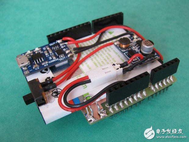
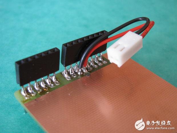
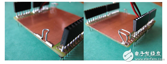
If you complete the above steps, you now have a separate battery module. It can be used in many different projects. This is why the battery module is not permanently attached to the prototype shield with glue. In the above example, the battery module is connected to the shield only through the "helper". These "holders" are shielded by curved metal paper clips and welded to "fake" prototypes.
This article is selected from the electronic enthusiast "Intelligent Industry Special", more quality content, download now

Easy Electronic Technology Co.,Ltd , https://www.pcelectronicgroup.com