Technical Application of Dual Tone Multi-frequency Transceiver MT8880 in Intelligent Communication Early Warning System
Using public telephone network to remotely control household appliances and dial alarms, the main problem to be solved is how to use telephone lines to transfer control information and how to process and process the information. The combination of Modem and computer can realize the transmission of control information, and the control information can be very complicated and rich, but a computer Modem must be set up between the controlling party and the controlled party, and the cost is relatively high. If the controlled party is easy to operate and requires less commands to achieve control, it is sufficient to directly control the remote controlled party by directly using the dual-tone multi-frequency signal on the telephone or a combination thereof.
1 System principle and composition
The main function of the telephone remote control system is to decode the dual tone multiple frequency (DTMF) signal of the telephone, and automatically drive the controlled electrical equipment to perform the specified operation, and the user can query the working status of the controlled equipment. , And when someone enters the room illegally by dialing the preset phone number for remote warning. Since this system uses a telephone for remote control, the system must be able to recognize the ringing signal on the telephone line to achieve automatic off-hook; at the same time, the system generally works under unattended conditions, so it must be able to automatically off-hook, Hang up, and when the user completes the operation and forgets to hang up, it must be able to automatically reset and shut down. For security reasons, it is necessary to add a password verification function; to perform work inquiries, there must be voice prompts and feedback. Combined request.
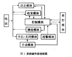
Based on the above requirements, this system is mainly equipped with a system opening and closing module, a system analog off-hook module, a voice module, a monitoring module, a DTMF transceiver module, a control module, and a controlled module, as shown in Figure 1. It is now described as follows.

1.1 System on / off module
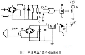
This system has multiple opening methods: ringing start, alarm start, manual start, as shown in Figure 2.

When the shutdown of this system is controlled by the single-chip microcomputer, after the single-chip microcomputer sends out a high-level signal, the triode is saturated, and the normally open end of the relay? K is closed, so that the K and A of the thyristor are short-circuited. The single-chip microcomputer sends out a low-level signal again, the triode intercepts, and the normally open end of the relay opens, making the K and A ends of the thyristor Q open, so that the thyristor enters the off state, and the power is turned off to shut down the system. When controlled manually, the triode is turned off when the switch is turned on, the normally open end of the relay is opened, and the system is powered off, thereby shutting down the system.
1.2 Analog off-hook module
When the MCU sends an off-hook signal, the transistor is saturated, the normally open end of the relay is closed, and the resistance at both ends of the telephone line is reduced to about 300 Ω, thereby realizing the analog off-hook. When the MCU sends the on-hook signal, the transistor is cut off, and the normally open end of the relay is opened, thereby realizing the simulation of on-hook.
1.3 Voice module
This module uses the new ISD4004 series recording and playback chip of American ISD company, which is composed of single chip microcomputer. The chip sound recording and playback adopts CchipCorder patented technology, that is, it can be directly stored without A / D conversion and compression, without A / D conversion errors, and can store 250-level sound signals in one recording bit (BIT), equivalent to the usual A / D D recorded 8 times. It integrates crystal oscillator, microphone preamplifier, automatic gain control, anti-aliasing filter, smoothing filter, etc., only a few external components are needed to form a complete sound recording and playback system.
1.4 Monitoring module
(1) Module overview
This module uses EEP pyroelectric infrared sensor. The principle is as follows: lead titanate ceramic has high thermoelectric coefficient and temperature stability, it can detect infrared rays. The sensor is sealed in the TO-5 housing, the pyrolysis component and the field effect tube are assembled together, and it can output a voltage proportional to the intensity of infrared radiation.
(2) Implementation of monitoring and alarm
When there is no one at home, when the MCU receives the alarm information from the monitoring system. The P3.0 port is set to a high level, the transistor T1 is saturated, and the relay J acts to realize analog off-hook. Then, after being confirmed as a dial tone by the trusted tone detection circuit, a command is sent from the P0 port, and the dial chip MT8880 turns the stored alarm number into a dual tone multi-frequency (DTMF) signal, which is fed back into the telephone line. After dialing, after completing the detection of busy tone, ringback and off-hook of the other party, the voice prompt circuit is activated to send an alarm voice signal to the line. If not, dial again.
1.5 DTMF transceiver module
(1) Module overview
This module is composed of MT8880 and single chip computer.
MT8880 is a single-chip DTMF transceiver with call progress filter. It is manufactured by MITEL's ISO2-CMOS process, with low power consumption and high reliability. The DTMF receiver in MT8880 is based on the single-chip receiver MT8870 industry standard and can receive all 16 DIMF signals. The DTMF transmitter uses a switched capacitor D / A converter with low signal distortion, high accuracy, and precise timing. MT8880 has two working modes: DTMF mode and call processing (CP) mode. When the call processing mode is selected, MT8880 is used to detect signal tones indicating different processes during the telephone call on the telephone network (mainly dial tone, the standard frequency of dial tone is 350 Hz or 440 Hz), and dial tone recognition can be performed. This is currently not available in other DTMF chips, so that a complex set of dial tone recognition circuits can be omitted.
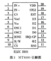
(2) Introduction to MT8880 (as shown in Figure 3)

IN +: operational amplifier input; IN-: operational amplifier input;
GS: Gain Select, operational amplifier output. High-speed gain for input signals;
Vref: reference voltage;
Vss: negative power supply;
OSC1: DTMF clock / oscillator input, using 3.579 545 MHz clock;
OSC2: clock output;
R / W: read and write control;
CS: chip selection;
RS0: register selection;
& 2: System clock input, TTL level;
IRQ / CP: Interrupt request / call processing, apply to MCU for interrupt. When the call processing mode is selected, the square wave signal corresponding to the call signal on the input signal line is output;
DO ~ D3: data cable;
Est: Early steering output, output before lag. When a valid audio pair is detected (also called signal condition Signal condiTIon), it becomes a high level, and it returns to a low level immediately when the signal condition is not met. A high level on this pin does not necessarily mean that there is a DTMF signal, and the voice signal will occasionally produce a valid audio pair.
St / Gt: Steering Output / Guard TIme output, lag output / output after protection. When the voltage is higher than VTST, (see the sending and receiving operation timing diagram), the detected audio pair is saved, and the content of the output latch is updated at the same time. When the voltage is lower than VTST, the chip can receive new audio again, which has an effect on the Gt output on the lag time constant (steering TImeconstant). Its state is a function of Est and the voltage added to St.
VDD: positive power supply.
(3) Realization of signal tone judgment
The principle of signal tone judgment is: dial tone due to the signal tone of the telephone system. The frequencies of the ring back tone and busy tone are sine waves of 425 ~ 475 Hz, but the intermittent ratio is different and there is a significant difference in time (dial tone continuous signal: busy tone is 0.35 s on, 0.35 s off, ring back is 1 s on, 4 s off). To judge the signal tone, the MT8880 chip that processes DTMF signals should be set to call processing mode first. When the call processing mode is selected, MT8880 cannot be used to detect DTMF signals. The call processing filter of MT8880 is a band-pass filter with a passband of 300 ~ 510 Hz. When a signal tone is input at the signal input, if MT8880 works in CP mode, it outputs a high level in IRQ / CP. The various signal tones in the telephone call process are filtered by MT8880, the square wave is obtained after the amplitude limitation, and the MT8880 IRQ is output. Then count the IRQ signal output by MT8880 for 5 s. The upper limit of dial tone count is (450 + 25) * 5 = 2375, and the lower limit of dial tone count is (450-25) * 5 = 2175. Similarly, the count range of busy tone is 1041 ~ 1212, the count range of ringback tone is 425 ~ 475, and the count of no signal should be 0.
In actual programming, considering the counting error and simplifying the program, the middle value of the adjacent counting limit of different signal tones is used to distinguish different signal tones. The count value is 2n and the count value is greater than 1792 as the dial tone. The busy tone is between 1024 and 1791, and there is no signal tone between 256 and 1023.
1.6 Control module
In order to improve the reliability and reduce the cost of this system, the AT89C51 microcontroller which has been widely used is adopted. It integrates 8 kB of FLASH on-chip, no external memory is required, and it is easy to use. The chip is compatible with 8051 instructions, easy to program, and powerful. In terms of hardware and programming, the P0 port is used to control the MT8880 chip, where P0.0 ~ P0.3 are the data input and output bits, and P0.4 ~ P0.7 are the MT8880 command word input bits; 5 bits in the P1 port To control the ISD4004 chip; use the P2 port to control household appliances; use the 3 bits in the P3 port to control the opening of the system, pick up the phone and set the flag.
1.7 Controlled module
Most home appliances use 220 V alternating current, which is a strong electric circuit. So use relays to switch appliances. The chip cannot directly drive the relay, so a circuit for driving the relay must be provided between the integrated circuit chip and the relay. All relays in this system use the two states of cut-off and saturation of the transistor to close or open the relay switch.
2 System software design
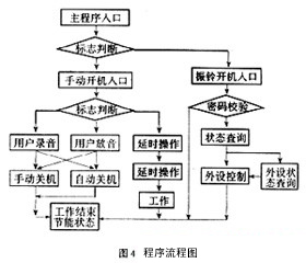
The software design of this system adopts modular design idea, and its program flow is shown in Figure 4.

The system's DTMF sending and receiving procedures are described as follows:
Receiving program: MOVR1, # 0
MOVR0, # 10H
LOOP1: MOVA, # 0FFH
MOVP0, A
SETBP0.7
SETBP0.4
CLRP0.5
SETBP0.6
MOVA, P0; read 8880 status register
JNBACC.2, LOOP1
CLRP0.4
MOVA, P0; read 8880 receive data register
ANLA, # 0FH; shield the upper four bits
MOV @ R0, A
INCR0
INCR1
CJNER1, # 07H, LOOP1
Code sending program: MOVR0, # 10H
MOVR1, # 7
MOVA, # 9DH; write 8880CRA
MOVP0, A
MOVA, # 90H
MOVP0, A; write 8880CRB, 8880 mode 2 is TONE, DTMF, IRQ, BURST
LOOP2: MOVA, @ R0
ORLA, # 0F0H
ANLA, # 8FH
MOVP0, A; send data
MOVA, # 0FFH
MOVP0, A
SETBP0.7
SETBP0.4
CLRP0.5
SETBP0.6
LOOP3: MOVA, P0; read 8880 status register
JNBACC.1, LOOP3
INCR0
DJNZR1, LOOP2?
3 Conclusion
The intelligent communication system formed by MT8880 has the advantages of fast communication speed, high reliability and low error rate. Since the system has been running, it works normally, has stable performance and reliable communication.
Aspheric Lens,Standard Aspheric Lens,Positive Meniscus Lenses,High Precision Aspheric Lens
Danyang Horse Optical Co., Ltd , https://www.dyhorseoptical.com