The seventh chapter is programming for the general interface. The content of this article is 7.4 temperature acquisition interface, 7.5 keyboard.
7.4 Temperature Acquisition Interface
> > > 7.4.1 Temperature sensor universal interface
AMetal provides a universal interface for temperature acquisition and contains only one temperature reading interface for reading the current temperature value. The function prototype is (am_temp.h):

Where handle is the handle of the temperature sensor, which can be obtained by initializing a specific temperature sensor (such as LM75), and p_temp is an output parameter for returning the current temperature value. To avoid fractional operations, a signed 32-bit integer is used here. The temperature value (in degrees Celsius) and its value is 1000 times the actual temperature value, indicating that the resolution of the temperature value is 0.001 °C. A sample program for reading temperatures is detailed in Listing 7.25.
Listing 7.25 am_temp_read() sample program

Obviously, in order for an application to read the temperature using the universal interface, it is necessary to acquire the handle of the temperature sensor, which requires a corresponding drive for the specific temperature sensor.
> > > 7.4.2 LM75B drive
The LM75B is a digital temperature sensor chip with an I2C interface from NXP Semiconductors. Ametal has provided its corresponding driver, which contains only one initialization function. The function prototype (am_temp_lm75.h) is:

This function is intended to take the instance handle of the LM75 temperature sensor and use the universal interface to read the temperature. among them:
P_lm75 is a pointer to an instance of type am_temp_lm75_t;
P_devinfo is a pointer to the instance information of the am_temp_lm75_info_t type.
Instance
An example of defining the am_temp_lm75_t type (am_temp_lm75.h) is as follows:

Where g_temp_lm75 is a user-defined instance whose address is passed as an argument to p_lm75.
2. Instance information
The instance information mainly describes the information related to LM75, namely the I2C slave address of LM75, etc. The definition of its type am_temp_lm75_info_t (am_temp_lm75.h) is as follows:

Among them, i2c_addr specifies the 7-bit slave address of the LM75 (in many applications, 8-bit data is often used to indicate the slave address, and the lowest bit of the 8-bit address is the read/write direction bit. Because of the read/write direction bit in AMetal The driver will automatically control the read/write direction bit without user control. Therefore, the 7-bit slave address provided by the user in AMetal does not include the read/write direction bit. The 7-bit slave address of the LM75 is 1001A2A1A0. The lowest three bits are determined by the A0~A2 pin level. In the AM824-Core, an LM75 temperature sensor is onboard. It can be seen that A0~A2 are connected to the ground and are low level. Therefore, the address of the onboard LM75 is 1001000, namely: 0x48. Its instance information is defined as follows:

Where g_temp_lm75_info is user-defined instance information whose address is passed as an argument to p_info.
3. I2C handle i2c_handle
Taking I2C1 as an example, the return value of its instance initialization function am_lpc82x_i2c1_inst_init() can be passed as an argument to i2c_handle. which is:

4. Example handle
Initialization of the LM75 is done based on the instance, instance information, and I2C handles. such as:

The return value of the initialization function is the handle of the temperature sensor. If the return value is NULL, the initialization fails. If the return value is not NULL, the valid handle is returned, which can be used as the parameter of the temperature reading interface. In order to facilitate the configuration of the LM75 (such as modifying the 7-bit slave address, etc.). Based on the modular programming idea, the definitions of initialization related instances, instance information, etc. are stored in the configuration file of the LM75, and the instance initialization function interface is extracted through the header file. The program examples of the source file and the header file are respectively shown in Listing 7.26 and the program. Listing 7.27.
Listing 7.26 LM75 Instance Initialization Function Implementation (am_hwconf_lm75.c)
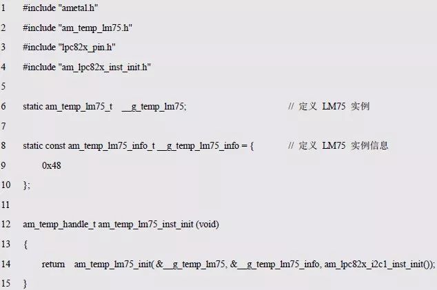
Listing 7.27 LM75 Instance Initialization Function Declaration (am_hwconf_lm75.h)

Subsequently only need to use the parameterless instance initialization function to complete the initialization of the LM75 instance, obtain the temperature sensor handle, that is, execute the following statement:

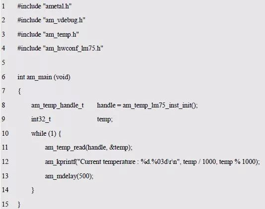
After the initialization is completed, the general temperature reading interface can be used to obtain the current temperature value. The sample program for reading and printing the current temperature value through the serial port is shown in Listing 7.28.
Listing 7.28 Sample program for detecting current temperature using the LM75
7.5 keyboard
> > > 7.5.1 Universal Keyboard Interface
Since the previous button processing method is fully coupled with the specific MCU, keyboard organization (independent button or matrix keyboard, etc.), AMetal provides a universal keyboard interface. Its function prototype is:

Where p_handler is a pointer to the key event handler, pfn_cb is a pointer to the user-defined key handler, and p_arg is the user parameter of the key handler.
P_handler
Am_input_key_handler_t is the type of button event handler, which is a type that is customized with typedef in the am_input.h file. which is:

Based on this, when using a button, you first need to define a key event handler instance (object) of this type, which essentially defines a structure variable. such as:

The instance's address &key_handler is passed as a parameter to the formal parameter p_handler of the function.
2. pfn_cb
Am_input_cb_key_t is the pointer type of the key handler, which is a type that is customized with typedef in the am_input.h file. which is:

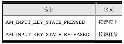
When a button event occurs (button press or button release), the button processing function pointed to by pfn_cb is called to complete the corresponding button processing function. When the function is called, the value passed to p_arg is the user parameter, and the value passed to key_code is the encoding of the key, which is defined in the am_input_code.h file using macros, such as KEY_1, KEY_2, etc., passed to key_state The value of the button is the status of the button, as shown in Table 7.5.
Table 7.5 Button Status
Take the AM824-Core development board as an example. The key code corresponding to the KEY is KEY_KP0. When the KEY button is pressed, LED0 is lit; when the KEY button is released, LED0 is off, and the corresponding button processing function is shown in Listing 7.29.
Listing 7.29 Button Processing Function Sample Program
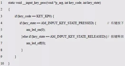
The function name can be passed as a parameter to the formal parameter pfn_cb of the am_input_key_handler_register() function.
3. p_arg
The value that is usually passed to the formal parameter p_arg by the am_input_key_handler_register() function is passed to the p_arg parameter of the event handler when the event handler callback function is called.
If not used, the value of p_arg is set to NULL when the am_input_key_handler_register() function is called, and the sample program for registering the key handler is shown in Listing 7.30.
Listing 7.30 Key Handling Function Sample Program
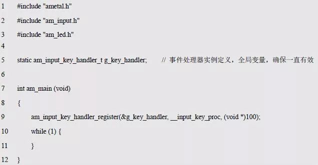
After registering the button processor, when a button is pressed or the button is released, the callback function specified when registering the button processor is called, which is the __input_key_proc() function in Listing 7.29. To separate the processing code for each key, multiple key event handlers can be registered, each processor handling one or more keys, as detailed in Listing 7.31.
Listing 7.31 Registering Multiple Button Processor Sample Programs
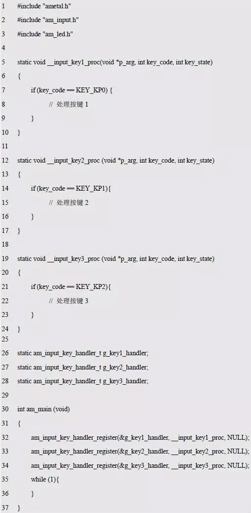
The general keyboard interface is characterized by shielding the underlying differences, making the application independent of the underlying MCU and the specific form of the keyboard, and can easily implement cross-platform applications.
In practical applications, keyboards come in a variety of forms, such as a GPIO-driven stand-alone keyboard (a keyboard of one or more separate buttons) and a matrix keyboard and a standard PS/2 interface keyboard, as well as ZLG's I2C interface ZLG72128 keyboard and keyboard made by digital tube driver chip. Although the detection methods of various buttons are different, the interfaces can be unified by providing the corresponding drivers. Just like when using an external device on a PC, you need to install the corresponding driver. AMetal provides drivers for common keyboards, and users can directly use details such as methods that do not care about button detection or button debounce.
> > > 7.5.2 Independent keyboard driver
The driver for the AMetal stand-alone keyboard provides an initialization function that can be used with the generic interface after initializing a separate keyboard instance. Its function prototype is:

Where p_dev is a pointer to an instance of the am_key_gpio_t type and p_info is a pointer to the instance information of the am_key_gpio_info_t type.
Instance
An example of defining the am_key_gpio_t type (am_key_gpio.h) is as follows:

Where g_key_gpio is a user-defined instance whose address is passed as an argument to p_dev.
2. Instance information
The example information mainly describes the information related to the independent keyboard, such as the GPIO pin number used, the number of independent buttons, and the corresponding key code. The definition of its type am_key_gpio_info_t (am_key_gpio.h) is as follows:

Among them, p_pins points to an array of pin numbers corresponding to each individual button. For example, on the AM824-Core development board, there is a multi-function button that can be used as a separate button. When J14's 1 and 2 are shorted, KEY is connected to PIO_KEY (PIO0_1). At this time, the button KEY is used as a separate button. Based on this, you can define an array that holds the pin numbers:

The address of this array can be used as the value of p_pins. Since the AM824 development board has only one independent button, the array has only one element, and its value is the pin number connected to the independent button, that is, PIO0_1. When there are multiple independent buttons, continue to add data elements after the array. Also, since the pin number is not modified after the system is booted, the const modifier is used.
In order to distinguish each button, each button is required to have a unique encoding value. Therefore, it is necessary to specify an encoding for each button in the independent keyboard. p_codes points to an array storing the corresponding encoding of each individual button, and the encoding is in the array pointed to by p_pins. Each individual button corresponds to one by one. For example, if you set the independent key corresponding code in the AM824ZB development board to KEY_KP0, you can define the following array:

The address of this array can be used as the value of p_codes. In the program example of the universal button processing interface, the key code KEY_F1 is used as the code of the independent key. The key code KEY_F1 is configured here. If you need to use other key codes, you can directly modify it. The key code can be any integer value, but it is recommended to use a standard key code like KEY_KP0, which is a macro defined in the am_input_code.h file.
Pin_num specifies the number of independent keys in a separate keyboard that should match the size of the array pointed to by p_pins and p_codes. There is only one independent button on the AM824-Core development board, so this value is 1.
For independent buttons, different circuits may affect the level when the button is pressed. In order for the driver to accurately obtain this information, the active_low member is used to indicate the level at which the button is pressed, and if the button is pressed, it is low. Then the value is AM_TRUE, otherwise the value is AM_FALSE. Looking at the corresponding schematic, the GPIO pin is low when the button is pressed, so the value of active_low should be set to AM_TRUE.
Scan_interval_ms specifies the time interval for the key scan, that is, a key detection is performed every other time to detect whether a key event occurs (key press or key release), which is usually set to 10 ms. Based on the above information, the instance information is defined as follows:
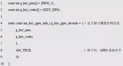
Based on the instance and instance information, the initialization of the independent keyboard can be completed. such as:

Once the initialization is complete, the button encoded as KEY_KP0 can be processed using the generic keyboard processing interface. In order to facilitate the configuration of a separate keyboard (modify instance information). Based on the modular programming idea, the definitions of initialization related instances and instance information are stored in the configuration file of the independent keyboard, and the instance initialization function interface is extracted through the header file. The program examples of the source file and the header file are respectively shown in Listing 7.32 and Listing 7.33.
Listing 7.32 Standalone keyboard instance initialization function implementation (am_hwconf_key_gpio.c)
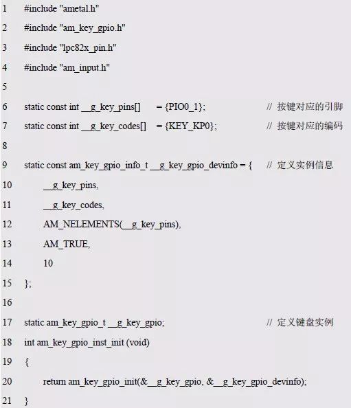
Listing 7.33 Standalone keyboard instance initialization function declaration (am_hwconf_key_gpio.h)

Subsequent only need to use the parameterless instance initialization function to complete the initialization of the independent keyboard instance:

Once the initialization is complete, the button encoded as KEY_KP0 can be processed using the generic keyboard processing interface.
In the AM824ZB, the stand-alone keyboard acts as an onboard resource, and the initialization of the independent keyboard has been performed by default at system startup. Therefore, in the sample program shown in Listing 7.30, the board can be used without calling the independent keyboard instance initialization function. Separate buttons.
If the user does not need to use the independent button, in order to save memory space, you can modify the AM_CFG_KEY_GPIO_ENABLE macro value in the am_prj_config.h project configuration file to 0, and trim the independent keyboard. This macro essentially controls a program in the board-level initialization function. See Listing 7.34 for details.
Listing 7.34 Principle of cropping a separate keyboard in board-level initialization
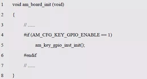
Note: The board-level initialization function is called automatically when the system starts. After the initialization is completed, it will enter the application entry, ie am_main().
> > > 7.5.3 Matrix keyboard driver
Similarly, the driver for the AMetal matrix button also provides an initialization function that can be used with a generic interface to initialize a matrix keyboard instance. Its function prototype is:

Where p_dev is a pointer to an instance of type am_key_matrix_gpio_softimer_t and p_info is a pointer to instance information of type am_key_matrix_gpio_softimer_info_t.
Instance
An example of defining the am_key_matrix_gpio_softimer_t type (am_key_matrix_gpio.h) is as follows:

Where miniport_key is a user-defined instance whose address is passed as an argument to p_dev.
2. Instance information
The instance information describes the information related to the matrix keyboard. The definition of the type am_key_matrix_gpio_softimer_info_t (am_key_matrix_gpio.h) is as follows:

The key_matrix_gpio_info member contains information about the GPIO-driven matrix keyboard; scan_interval_ms specifies the time interval (in milliseconds) for the key scan, that is, the key detection is performed every other time to detect whether a key event occurs (key press Or press the button release), the value is generally set to 5 ms.
The key_matrix_gpio_info type am_key_matrix_gpio_info_t is defined (am_key_matrix_gpio.h) as:

Among them, the base_info member contains the basic information of the matrix keyboard, such as the number of rows and columns of the matrix keyboard, the encoding corresponding to each button. P_pins_row points to an array of pin numbers corresponding to the matrix keyboard row lines, and p_pins_col points to an array of pin numbers corresponding to the matrix keyboard column lines.
When using MiniPort-Key to connect to AM824-Core, KR0 and KR1 are row lines, which are connected to PIO0_6 and PIO0_7 respectively. KL0 and KL1 are column lines, which are connected to PIO0_17 and PIO0_23 respectively. Define the row line pin array and column line pin array as:

The addresses of the two arrays can be used as the values ​​of p_pins_row and p_pins_col, respectively.
The type of the base_info member am_key_matrix_base_info_t is defined as (am_key_matrix_base.h) as follows:

Among them, row and col represent the number of rows and columns of the matrix keyboard respectively. If the MiniPort-Key matrix keyboard is used, it is a 2×2 matrix keyboard, so the number of rows and the number of columns are both 2.
P_codes points to the array of codes corresponding to the keys in the matrix keyboard. In order to match the hardware labels, the codes assigned to each button are: KEY_0, KEY_1, KEY_2, KEY_3. Then you can define the following array:

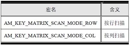
The address of this array can be used as the value of p_codes. Active_low indicates whether the button press is low. According to the design of the circuit, the row line is connected with a pull-up resistor. When configured as the input mode, it will be high by default. Therefore, the low-level drive mode should be used, and the column line output is low. When the button is pressed, a low level is detected, that is, the value should be AM_TRUE. Scan_mode indicates the scanning mode. The supported methods include row scanning and column scanning. The corresponding macro names are shown in Table 7.6. If a column scan is used, the value is AM_KEY_MATRIX_SCAN_MODE_COL. Based on
On the information, the complete instance information can be defined as follows:
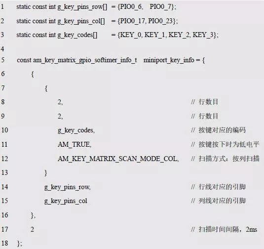
Table 7.6 Matrix Keyboard Scanning Method
Based on the instance and instance information, the initialization of the MiniPort-Key matrix keyboard can be completed. such as:

Once the initialization is complete, the generic keyboard processing interface can be used to process the keys encoded as KEY_0~KEY_3. In order to facilitate the configuration of the matrix keyboard (modify instance information). Based on the modular programming idea, the definitions of initialization related instances, instance information, etc. are stored in the configuration file of the independent keyboard, and the instance initialization function interface is extracted through the header file. The program examples of the source file and the header file are respectively shown in Listing 7.35 and Listing 7.36.
Listing 7.35 Matrix Keyboard Instance Initialization Function Implementation (am_hwconf_miniport _key.c)
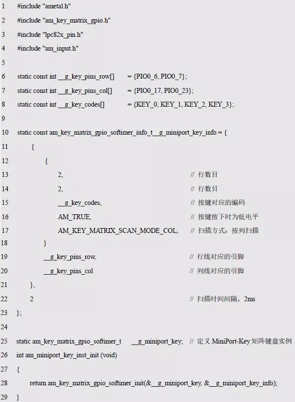
Listing 7.36 Matrix Keyboard Instance Initialization Function Declaration (am_hwconf_miniport_key.h)

Subsequent only need to use the parameterless instance initialization function to complete the initialization of the matrix keyboard instance:

When the initialization is complete, the button encoded as KEY_0~KEY_3 can be processed using the generic keyboard processing interface. In the AM824-Core, the matrix keyboard is an optional palette resource. The initialization operation is not performed by default when the system is started, so if you need to use the matrix keyboard, you must manually call the matrix keyboard instance initialization function.
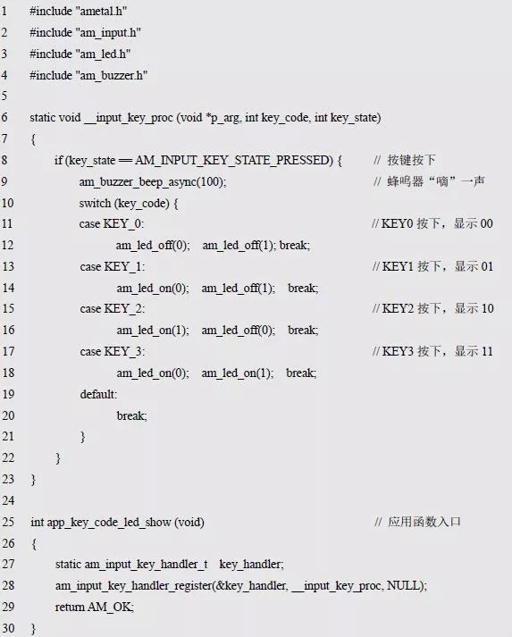
Write a simple application based on the button universal interface: When a button is pressed, the buzzer displays the button number by a combination of LED0 and LED1 while making a "beep" sound. For example, when the KEY0 button is pressed, both LEDs are off. When KEY1 is pressed, 01 is displayed, that is, LED0 is on, LED1 is off, and so on. Store the application in the app_key_code_led_show.c file with the interface declaration in the app_key_code_led_show.h file, as described in Listing 7.37 and Listing 7.38.
Listing 7.37 Matrix Keyboard Application Implementation (app_key_code_led_show.c)
Listing 7.38 Matrix Keyboard Application Interface Declaration (app_key_code_led_show.h)

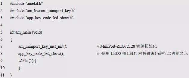
The main program that demonstrates the functionality of this application using the four buttons of the MiniPort-Key is shown in Listing 7.39.
Listing 7.39 Matrix Keyboard Application Main Program
SMT Feeder types,
1. different smt machines with different smt feeders, but different model of the same brand machine can use the same feeder,like Panasonic Feeder.
2. Base on the size and types of components, smt feeder could be divided into three types : Tube feeder; Tray Feeder; Bulk Feeder.
Tape feeders with the different size such as 8mm, 16mm, 24mm, 32mm, 44mm, 56mm etc.
3. Base on the feeder condition, smt feeder also could be divided into four types: original new SMT feeder parts, used original SMT feeder parts, imitation/copy new SMT feeder parts, imitation/copy used SMT feeder parts,
Original feeder is made by original smt machine production manufacturers. Due to the large demand for smt feeder, currently there are many copy new feeders parts. Our feeders quality is also very great and looking forward to your cooperation!
Feeder Parts,Smt Feeder Parts,Panasonic Feeder Parts,Parts For Panasonic Feeder
Shenzhen Keith Electronic Equipment Co., Ltd. , https://www.aismtks.com