1, the feeling of shielding effectiveness
Shielding is a technique that uses shields to block or reduce the transmission of electromagnetic energy and is one of the important means to suppress electromagnetic interference. Shielding has two purposes. One is to limit the electromagnetic energy radiated inside the limit to the internal area, and the other is to prevent external radiation from entering a certain area.
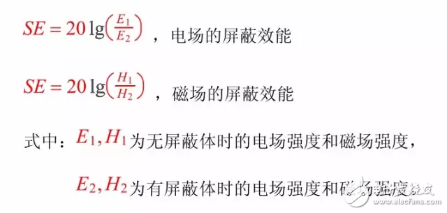
When the electromagnetic field is isolated by the metal material, the strength of the electromagnetic field will be significantly reduced. This phenomenon is the shielding effect of the metal material. We can use the ratio of the strength of the electromagnetic field in the same position without the shield to the strength of the electromagnetic field after the shield is added to characterize the shielding effect of the metal material, and define the shielding effectiveness (Shielding EffecTIveness, SE for short):

2. Influence of the hole on the shield
In fact, various defects such as various slits, openings, and cables are inevitably present on the shield, and these defects have a drastic deterioration effect on the shielding effectiveness of the shield.
The shielding effectiveness of the ideal shield analyzed in the previous section above 30MHz is already high enough, far exceeding the actual needs of the project. The factors that really determine the shielding effectiveness of the actual shield are various electrical discontinuities, including: gaps, openings, cable penetration, and the like.
The gaps above the shield are very common. Especially in the current cabinets and plug-ins, the assembly method is adopted. There are many gaps. If the treatment is not proper, the gap will greatly deteriorate the shielding effectiveness of the shield.
3, the overall design idea of ​​the hole seam shielding
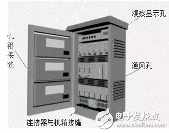
According to the theory of small hole coupling, there are two main factors that determine the amount of leakage of the hole: the area of ​​the hole and the maximum line size of the hole. If both are large, the leakage is the most serious; if the area is small and the maximum line size is large, the electromagnetic leakage is still large. As shown in the figure, a typical cabinet diagram is divided into four categories:

(1) Chassis (cabinet) seam
Although the size of the seam is not large, the maximum thread size, that is, the seam length is very large. Due to the limitations of maintenance and opening, the seam becomes the most difficult type of hole in the electronic equipment, and the conductive gasket is used. Special shielding materials can effectively suppress electromagnetic leakage. The key to this type of hole-slot shielding design is to reasonably select the conductive gasket material and perform appropriate deformation control.
(2) ventilation holes
This type of hole area and maximum line size is large, and the key to the design of the vent is the selection of the ventilation components and the design of the assembly structure. Under the condition of satisfying the ventilation performance, shielded ventilation parts with higher screen efficiency should be selected as much as possible.
(3) observation hole and display hole
The hole area and the maximum wire size of this type are large, and the key to the design is the selection of the shielding light-transmitting material and the design of the assembly structure.
(4) Connector and chassis seam
The area of ​​the slit and the maximum dimension are not large, but the contact impedance of the connector and the chassis is sharply increased at high frequencies, so that the common mode conduction emission of the shielded cable becomes large, which often leads to radiation of the entire device. The emission has exceeded the standard, and a conductive gasket such as a conductive rubber should be used for this purpose.
Since the radiation source is divided into the near-field electric field source, the magnetic field source and the far-field plane wave, the shielding performance of the shielding body is different depending on the radiation source, in terms of material selection, structural shape and leakage control of the aperture. In order to achieve the required shielding performance in the design, it is necessary to first determine the radiation source, clarify the frequency range, and then determine the control elements according to the typical leakage structure of each frequency band, and then select the appropriate shielding material to design the shielding shell.
In summary, the design points of the hole suppression are summarized as follows:
(1) Reasonable selection of shielding materials;
(2) Reasonably design and install the interconnection structure.
4. Evaluation of hole leakage
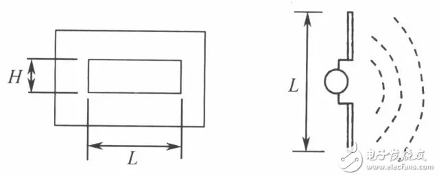
Inevitably, there are various holes in the chassis that ultimately determine the shielding effectiveness of the shield (assuming no cables pass through the chassis). It is generally believed that the shielding effectiveness of the shielded chassis at low frequencies depends primarily on the material from which the shield is fabricated. The shielding effectiveness at high frequencies depends primarily on the holes and gaps in the chassis. When an electromagnetic wave is incident on a hole, the hole acts as a dipole antenna. When the length of the slit reaches 1/2, the radiation efficiency is the highest (regardless of the width of the slit). That is, it can radiate out all the energy incident on the gap, as shown.

In the far field, if the maximum dimension L of the hole is less than λ/2, the shielding effectiveness of the gap on a material having a thickness of 0 is:
![]()
If L is greater than λ/2, then SE = 0 (dB).
SE—the shielding effectiveness (dB);
L──the length of the hole (mm);
H—the width of the hole (mm);
f──The frequency of the incident electromagnetic wave (MHz).
This formula calculates the shielding effectiveness of the worst case (the direction of polarization that causes the largest leakage). In practice, the shielding effectiveness may be higher.
In the near field, the leakage of the hole is also related to the source of the magnetic field. When the radiation source is an electric field source, the leakage of the hole is smaller than the far field (the shielding effectiveness is high); and when the radiation source is the magnetic field source, the leakage of the hole is larger than the far field (the shielding effectiveness is low). For radiation sources with different circuit impedances Zc, the formula is as follows:
If ZC>(7.9/Df): (electric field source)
![]()
If ZC<(7.9/Df): (electric field source)
![]()
SE—the shielding effectiveness (dB);
L──the length of the hole (mm);
H—the width of the hole (mm);
f──The frequency of the incident electromagnetic wave (MHz).
This formula calculates the shielding effectiveness of the worst case (the direction of polarization that causes the largest leakage). In practice, the shielding effectiveness may be higher.
The problem to be aware of is that for magnetic field radiation sources, the shielding effectiveness of the holes in the near-field region has nothing to do with the frequency of the electromagnetic waves, that is, small holes can also cause large leakage. A more important parameter affecting the effectiveness of the shielding at this time is the distance from the hole to the radiation source. The closer the hole is to the radiation source, the greater the leakage. This feature often leads to accidental leakage of the shield. Since one purpose of opening a hole in the shield is to ventilate heat, this means that the hole is naturally designed to be close to the heat source, and the heat source is often a carrier of a large current with a strong magnetic field around it. As a result, the holes are unintentionally opened in the vicinity of the strong magnetic field radiation source. Therefore, in the design, it is necessary to pay attention to the holes and gaps away from the current carrier, such as circuit boards, cables, transformers and so on.
When N holes of the same size are arranged together and are close together (distance is less than λ/2), the shielding effectiveness of the hole array is reduced, and the drop value is 10 lgN.
Because the radiation of the holes is directional, the holes on different faces do not significantly increase the leakage. This feature allows the holes to be placed on different sides of the shielded chassis during design to avoid excessive radiation from a certain surface.
With the advent of 5G era, people put forward higher requirements on all aspects of indoor coverage. Due to difficulties in deployment and limited capacity growth, the traditional Das solution is not suitable for the development trend of 5G. The 4G distributed pick-up station can support 5G NR through modification. Project implementation is relatively simple, can achieve 4 × 4. MIMO has excellent capacity and performance, suitable for a variety of scenarios of 5G indoor coverage. This paper studied the layout position of Pico RRU in distributed Pico base station construction scheme, and designed the Pico RRU automatic layout function based on genetic algorithm in the drawing, in order to improve the efficiency of indoor power distribution system design
ISDB Antenna,ISDB-T Antenna,ISDB Antenna for Car,IDSB antenna for Japan
Yetnorson Antenna Co., Ltd. , https://www.yetnorson.com