The GPRS-based remote security monitoring system designed here is that the video signal transmitted by the camera is compressed and encoded and transmitted to the built-in Web server through the internal bus. On the monitoring side, the user can directly view the camera video image on the web server through the browser, and the authorized user can also control the action of the monitor. In this way, the remote control of the monitoring point is realized, and the monitoring machine is conveniently controlled by the browser.
1 Overall design
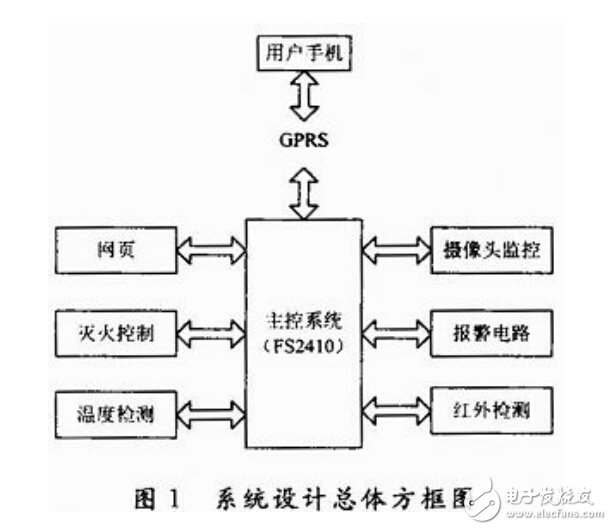
The system uses the ARM 9 processor S3C2410 as the MCU as the controller, which is responsible for collecting data from the infrared sensor, temperature sensor and camera, and controlling the execution of alarm measures and fire-fighting measures, sending text messages to users through the GPRS module, and the monitoring machine can pass the Internet. The webpage interacts with the webpage, and the user can control the monitor by logging in to the webpage, and the monitor can transmit the collected data to the webpage through the web server. The overall design framework of the system is shown in Figure 1.

2 hardware circuit design
2.1 main control circuit design
The main control system circuit is mainly composed of Samsung's processor S3C2410. The peripherals connected to the main control circuit include camera, GPRS module, temperature acquisition module, buzzer alarm module, fire extinguishing module and infrared sensor module. The processor continuously uses the polling method to read data from the temperature acquisition module and the infrared sensing module. When the read temperature value exceeds the set threshold value, or the infrared sensing module is interrupted, the home has a fire. Or a thief appears in the home, the processor will drive the buzzer alarm module alarm at this time, and send an alarm message to the user through the GPRS module. The processor also captures the camera's video stream while processing these actions.
2.2 Alarm circuit design
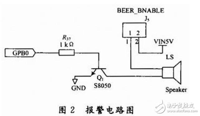
First connect the buzzer to a GPB0 pin on the S3C2410 processor. First configure GPB0 of GPBCON to output mode when 1 is written to the data register. The buzzer turns on and writes 0 to turn off the buzzer. The software is controlled by ioctl. The alarm circuit is shown in Figure 2.

2.3 Temperature acquisition circuit design
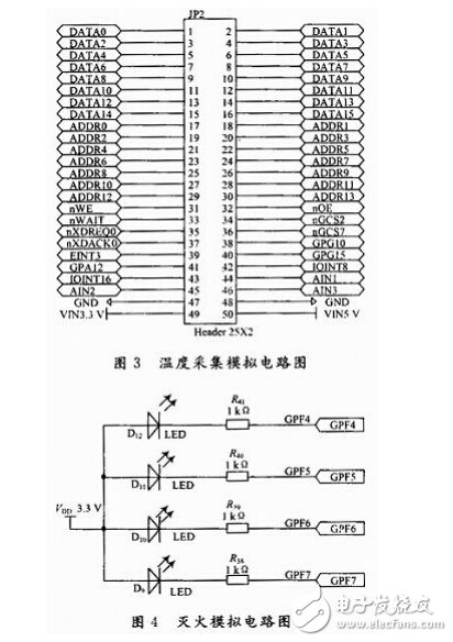
The temperature value is obtained from the temperature sensor by the main control board, and the obtained temperature value is converted by the A/D converter and transmitted to the main control board. The A/D converter is the interface between the analog signal source and the CPU. Its task is to convert continuously changing analog signals into digital signals for use by computers and digital systems. The A/D converter for the FS2410 development board is a 10-bit A/D converter that comes with the ARMS3C2410. And support touch screen function. The maximum conversion rate is 500 kHz, and the A/D converter frequency is calculated as: System clock / (proportional value + 1). The characteristic of this circuit is to simulate the change of temperature by changing the resistance of the sliding varistor to change the analog voltage. The software reads and writes A/D through read and write. The temperature acquisition analog circuit is shown in Figure 3.

Pcb Terminal Block,Pcb Barrier Terminal Blocks,Pcb Terminal Block Connector,Barrier Terminal Blocks And Connectors
Sichuan Xinlian electronic science and technology Company , https://www.sztmlchs.com