Microcontrollers are used as the main control element for almost every application. Their power and flexibility allow them to go to the heart of most designs of components. The key to building an MCU for efficient design often relies on a trade-off between power consumption and performance. Many MCUs offer several options that can limit the MCU clock rate, so its performance is powered by the MCU. Understanding the public relationship between operating voltage and operating clock rate can be key to how to get the most out of your next MCU design. This article will quickly review some of the common options for powering MCUs and discussing implementations that are likely to result in constraints. Modify the working voltage to get the best combination of performance and energy efficiency at runtime to explore common techniques to help you select and implement your next MCU-based design.
Frequency and operating voltage - a key performance consideration
The most fundamental relationship between performance and power consumption is the voltage at which the MCU operates. The operating power is directly related to the operating voltage (defined by the power equals the voltage multiplied by the current), so clear the action power requirements, you will use your design MCU to decide when is a key consideration. You might think that this means you should always use the lowest power MCU, but if performance is all the problem in the design, you will need to consider the operating frequency as a key element, and the operating frequency of an MCU is often limited. Operating Voltage. Many MCU manufacturers understand the importance of the relationship between operating voltage, operating frequency, MCU performance, and MCU operating power, and they provide different levels of operating power and operating frequency to make it easier to optimize the design for optimal fit. To the system requirements. As an example, the Renesas RL78 MCU has four different operating voltage ranges, each supporting a different operating frequency, as shown in Figure 1 below. At 1.6 V and 1.8 V, the RL78 can operate anywhere between 1 MHz and 4 MHz. Between 2.7 V and 5.5 V, it can operate up to 20 MHz. Therefore, the RL78 can operate up to five times faster, and if it uses 2.7 V instead of 1.8 volts, the operating supply voltage is only increased by 50%.

Figure 1: Voltage and frequency diagram Renesas RL78 MCU.
When improving the above relationship of power efficiency, working at higher voltages is common in many MCUs, and understanding that power efficiency is one of the most important relationships in design is the most important relationship. In many cases, it saves more power to keep the MCU in the lowest possible power state, maybe a low sleep mode, when it needs to do some processing (maybe sampling sensor to take further action, see its wake up Need to take). When it is needed to process it is usually more power efficient to run at a faster frequency to minimize the time in the higher power state. If the process can achieve 5 times the speed and only need to increase the operating power by 50% (as in the case of RL78), it can be clearly seen that the total energy required will be much less, so this will be a More energy efficient design.
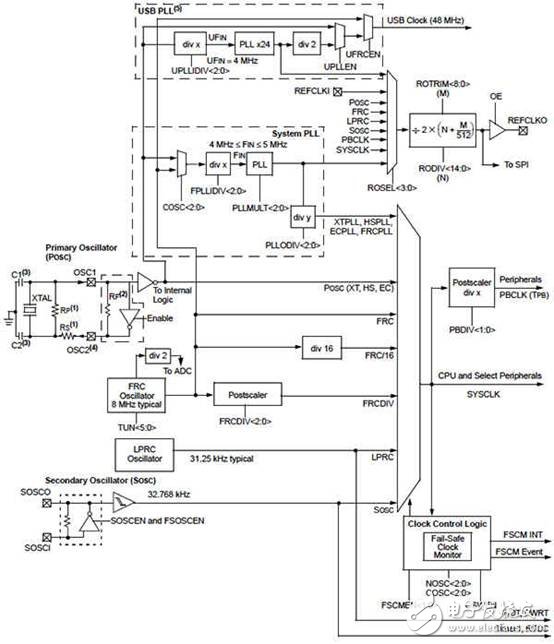
The frequency of the clock-controlled MCU operation is managed by a clock control block; and many clock control blocks have functions that can be used to select, control, and manage the clock source of the CPU, memory, peripherals, and analog modules. By controlling the clock frequency, these blocks, even the off clock function, are not modulated by the amount of dynamic current used in a particular processing routine (the required current to change the voltage level of a signal or storage element) can be modulated so that you The current used is in the most efficient way. (Note that battery-based applications, in particular, are the latest conscious design because it is the total current supplied from the battery that is usually the most critical constraint). Many of the most common and useful clock control functions are included in Microchip's PIC32MX microcontroller clock control block. For most clock control modules, the starting point shown in Figure 2 is the clock source, and by having multiple sources it makes it possible to optimize independently. The clock is a plurality of modules.
For example, the PIC32MX has a low-power internal RC oscillator (near the bottom of the LPRC Figure 2) that can be used when very low speed operation is acceptable. It can provide a watchdog timer (WDT) so that even in very low power mode this critical timer can still be used. The main oscillator (POSC) uses an external crystal to generate the precise high-speed clock source from the highest performing part of the device, and the system and USB phase-locked loop (at the top of the figure). Note that a separate PLL also means that USB operation can be independent of the system clock, providing an optimized clock and potential power savings. The Fast RC Oscillator (FRC) specifies that if an external oscillator 8 MHz clock source is not required, the maximum frequency and accuracy is not needed to save board space, component count, and perhaps power savings. Finally, the secondary oscillator can be used for low power operation from an external 32 kHz crystal.

Figure 2: PIC32MX1XX Home Clock Control Module at Microchip.
Tractor Autopilot Navigation,Gps Navigation System,Gps Autopilot,Unmanned Driving System
Xuzhou Jitian Intelligent Equipment Co. Ltd , https://www.jitianequipment.com