Integral circuit

The circuit structure is shown in Figure J-1. The integrating circuit can convert a rectangular pulse wave into a sawtooth wave or a triangle wave, and it can also convert a sawtooth wave into a parabolic wave. The circuit principle is very simple, which is based on the principle of capacitor discharge and discharge. I wo n’t go into details here. The time constant R * C of the circuit is mentioned here. The condition for forming an integrating circuit is that the time constant of the circuit must be greater than or equal to 10. Double the width of the input waveform.

Follow WeChat

Download Audiophile APP

Follow the audiophile class
related suggestion
The function of the integral circuit The integral circuit and the differential circuit perform the opposite function: they can extract the average value of the input signal, that is, the low frequency component. ...
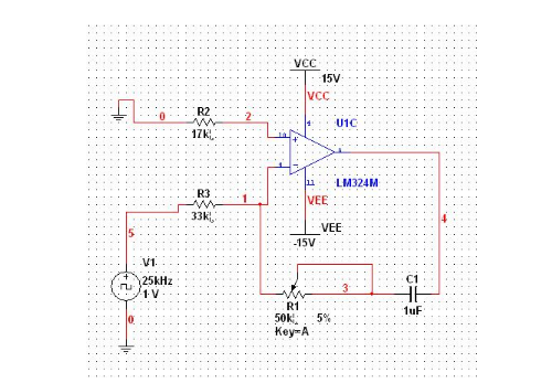
The integration circuit is mainly used for waveform transformation, elimination of the offset voltage of the amplifier circuit and integration compensation in the feedback control.

No matter what works you design, the buttons are always indispensable. What do you know about the buttons? The usual switch used for the button is a mechanical elastic switch, when ...
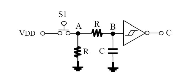
Because the voltage across C1 cannot be abruptly changed, during the rising edge of the input signal to the flat top, the input signal charges C1 through R1, and the voltage across C1 is due to the charge ...

The following figure is a typical integration circuit diagram. It can be seen from the figure that the input signal passes through a resistor and flows back to the capacitor through feedback, but at this time, the capacitor is considered ...
The circuit whose output signal is proportional to the integral of the input signal is called an integrating circuit. Integrating circuit is mainly used for waveform transformation, elimination of offset voltage of amplifying circuit ...
The prerequisites of the integration circuit to form an integration circuit require the time constant of the integration circuit itself. The frequency cycle of the input signal, that is, C1 will not be charged during work ...

When the rectangular pulse is used as the excitation source of the RC series circuit, select a different time constant and output terminal, we can get some kind of output waveform we want, ...
The integration circuit converts the input square wave into a triangular wave or a ramp wave, which is mainly used for waveform transformation, elimination of the offset voltage of the amplifier circuit, and integral compensation in feedback control ...

The integral circuit is a circuit that makes the output signal proportional to the time integral value of the input signal. The integral circuit is mainly used for waveform transformation and elimination of the offset voltage of the amplifier circuit ...
The circuit whose output voltage has a differential relationship with the input voltage is a differential circuit, usually composed of a capacitor and a resistor; the output voltage has an integral relationship with the input voltage ...
The circuit structure is shown in Figure W-1. The differential circuit can convert a rectangular wave into a sharp pulse wave. The output waveform of this circuit only reflects the sudden part of the input waveform, that is, only ...

Function of compound high-speed integration circuit that can be applied in CR oscillator of several MHz

The function of an integral circuit circuit with approximately ideal characteristics
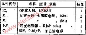
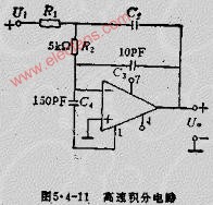
High-speed integration circuit When the time constant T1 of the Miller integration circuit is small, that is, in the case of high-speed operation, the actual output wave waveform lags behind the theory ...
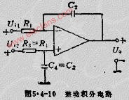
If the differential integration circuit is to integrate the difference between the two voltages, the differential integration circuit shown in Figure 5.4-10 can be used. Its output voltage is related to two ...
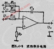
The summing integration circuit uses a simple integrator to easily form a summing integrator. In the circuit of Figure 5.4-9, the capacitor consists of all that flows into the virtual place ...
The actual integration circuit can be seen from Figure 5.4-6B, curve 1 is the characteristic curve of the ideal integration circuit, curve 2 is the characteristic curve of the actual integration circuit ...
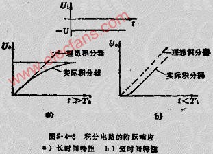
Basic integration circuit The basic integration circuit has an inverting structure, its input loop component is a resistor, and the feedback loop component is a capacitor, see Figure 5.4-6 ...
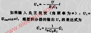
What is the integration circuit The integration circuit is shown below: The circuit structure is as shown above, the integration circuit can be rectangular

Integral circuit principle: From the picture, Uo = Uc = (1 / C) ∫icdt, because Ui = UR + Uo, when t = to, U ...


1. Differentiation circuit The output signal is proportional to the differential of the input signal ...
