In recent years, with the rapid development of wireless communication technology, low-cost, miniaturized, wide-band multi-frequency antennas have become the modern wireless coverage of 2. 4~ 2. 485/ 5. 15~ 5. 35/ 5. 725~ 5. 825 GHz.
Microstrip antennas have received wide attention due to their advantages of light weight, low profile, and small size. In particular, the application of wireless local area network (WLAN) requires a broadband miniaturized antenna capable of providing multi-band operation, and WLAN has been widely used in existing microwave communication systems. In recent years, WLAN antennas have been extensively studied at home and abroad.
The literature proposes a wide-band E-shaped microstrip antenna for 5-6 GHz wireless communication, but only works in a single frequency band and cannot meet the dual-band coverage of WLAN. Based on the literature, a dual-band microstrip antenna composed of an E-shaped microstrip patch antenna and a microstrip dipole is introduced. The antenna directly generates two bandwidths by means of slot coupling and radio wave steering. It satisfies the dual-band communication requirements of WLAN and HIPERLNA ( 5. 15~ 5. 35 GHz and 5. 47~ 5. 825 GHz) while meeting the communication requirements of IEEE 802.11 a/ b/ g, and The structure is simple, easy to design and manufacture. The radiating portion of the antenna mainly consists of an E-shaped microstrip patch and a microstrip dipole. The electromagnetic simulation software CST is used to study the resonant characteristics and pattern characteristics of the designed antenna. The simulation results show that the antenna can meet the dual-band communication requirements of WLAN, and the gain is improved compared with similar antennas.
1 Antenna structure and designThe basic structure of the antenna is shown in Figure 1. The entire antenna is made of 40 & TImes; 40 mm2 foam (dielectric constant is 1.07, close to the dielectric constant of air). The height of the dielectric plate is 5 mm. The thickness of the E-shaped microstrip patch and the microstrip dipole patch is 0.2 mm, and the grounding plate is made of 0.2 mm copper to ensure sufficient support strength of the antenna.
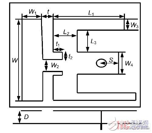
Figure 1 The basic structure of the antenna
As can be seen from Figure 1, the basic structure of the antenna consists of an E-shaped microstrip patch and a microstrip dipole. The two end arms of the E-shaped microstrip patch are of equal length with a coaxial feed port in the middle. The waves are evenly distributed across the E-shaped microstrip patch and dipole through the feed port, causing the patch to produce two resonant frequencies. The coupling gap t, width W2, W1 and W determine the dipole radiation, producing a resonant frequency in the low frequency band. The E-shaped microstrip antenna generates the resonant frequency of the antenna at a high frequency band, the dipole microstrip antenna resonates at a low frequency band, and the two radiation sources share a coaxial feed.
Figure 2 shows the current distribution of the designed antenna. It can be seen from Fig. 2(a) that the electric wave is guided by the connecting transmission line embedded in the E-shaped microstrip patch and the coupling of the slit t, which generates strong radiation on the dipole, making the bandwidth of the microstrip dipole Increased to meet the communication needs of IEEE 802.11b/g. It can be seen from Fig. 2(b) that the current is evenly distributed on the two arms of the E-shaped microstrip patch, which increases the distribution length of the current, so that the E-antenna has a large bandwidth, which can satisfy 5. 1~5. The need for 825 GHz wireless communications.
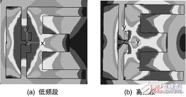
Figure 2 Current distribution of the antenna
2 Simulation results and analysisAccording to the above analysis, the E-shaped microstrip patch antenna and the microstrip dipole combination are used to design and simulate the WLAN antennas operating at 2.4 to 2.483 GHz and 5.1 to 5.825 GHz. And optimization.
The electromagnetic simulation software CST is used for modeling and simulation. Considering the consistency between simulation and actual engineering, the dielectric constant of the dielectric plate between the radiation plate and the ground plate is directly set to 1 07 when modeling. The two resonance points obtained by the simulation have frequencies of 2 44 GHz and 5 46 GHz. The simulation results are shown in Table 1.
As can be seen from Table 1, the antenna has higher radiation efficiency and gain at 2 resonance points. Since W1 and W2 are the width of the dipole antenna and the feed transmission line width of the dipole antenna, t is the coupling gap between the E-shaped microstrip patch and the dipole microstrip patch, so for W1, W2 and t Optimized, the return loss curves for different widths are shown in Figure 3~ Figure 5. As can be seen from Figure 3, when W1 is adjusted, the low frequency band of the antenna will increase with the increase of W1, and the frequency of the antenna will increase. As can be seen from Figure 4, when W2 is adjusted, the coupling capacitance between the dipole antenna and the E-shaped microstrip patch and the impedance of the feed transmission line are changed, so that the resonance point of the antenna is shifted. When W1 = 6. 5 mm, W2 = 1. 9 mm, the resonant impedance bandwidth of the antenna is the largest, and the resonant frequency of the antenna is 2.44 GHz and 5.46 GHz, and the bandwidth is 83 MHz and 812 MHz, respectively.

Simulation results of antenna direction parameters
It can be seen from Fig. 5 that the gap t between the E-shaped microstrip patch and the microstrip dipole antenna has a small influence on the working bandwidth of the antenna when the pitch is greater than 1.5 mm. The structural parameters of the antenna after optimization using the electromagnetic simulation software CST are: L1 = 25. 5 mm; L 2 = 6. 8 mm; L3 = 8 mm; W = 32 mm; W1 = 6. 5 mm; W2 = 1. 9 Mm; W3 = 4 mm; W4 = 8 mm; t = 2. 5 mm; t 1 = 1. 8 mm; t 2 = 3. 6 mm; S = 4 mm. It can also be seen from Fig. 4 that the high frequency band of the antenna is basically independent and has little influence on the embedded feed transmission line, so the dual frequency antenna can be independently designed.
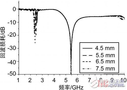
Figure 3 Effect of W1 on the parameters of the antenna
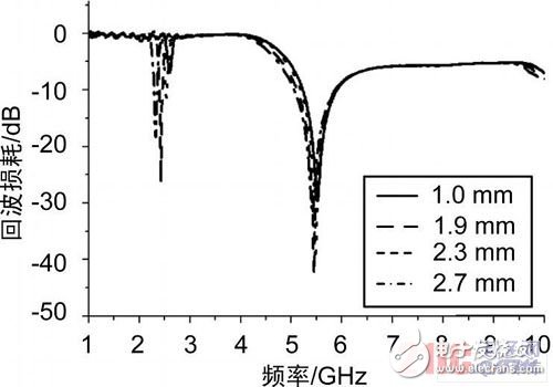
Figure 4 Effect of W2 on the parameters of the antenna
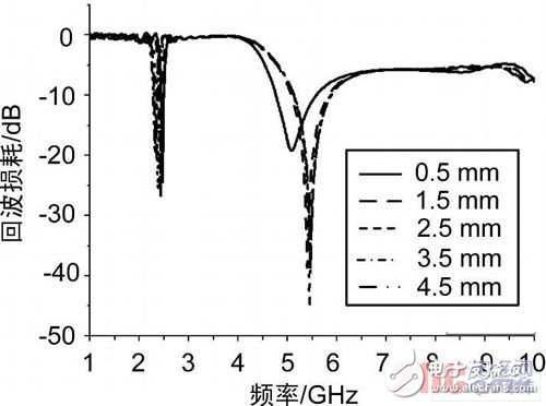
Figure 5 t Effect on antenna parameters
Samsung Screen Protector,Tempered Glass Samsung,Mobile Tempered Glass,Tempered Glass Screen Protector Iphone Samsung
Shenzhen TUOLI Electronic Technology Co., Ltd. , https://www.hydrogelprotectors.com