Unlike a processor, power supplies can look at specifications and performance; power supplies are not like video cards, and a key GPU determines the quality. In addition to meeting power requirements, a good power supply must also consider factors such as stability, energy saving, quietness, and security. In the absence of professional equipment for testing, we can understand the basic principles and components of some power supplies in order to achieve "at a glance."
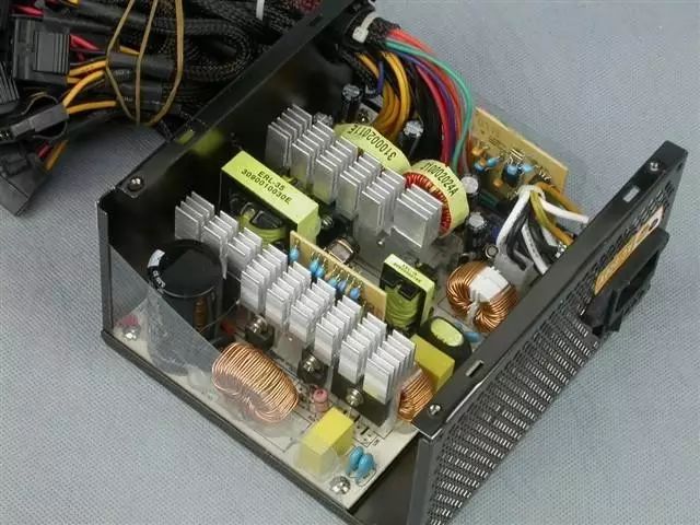
Grab the key and stop dizzy
From the outside it looks like the power source is a bit bigger than a "brick", but its "belly" stuff can be quite a lot. When we open the enclosure, we can see hundreds of various electronic components and complex intertwined cables. As the saying goes, "The thief must first dispose of the king." When observing the power supply, we should also pay attention to the following sections.
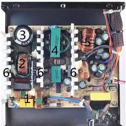
The internal structure diagram of a power supply, numbered 1 to 6 identifies the part that everyone should focus on.
1, one, two EMI filter circuit. The role of this part is to filter the electricity from the external grid and obtain relatively pure AC for subsequent use.
2, PFC circuit. Its role is to reduce harmonics during the conversion of AC power into DC power, reduce the interference to the indoor power grid and the utility grid, and reduce the loss of utility power.
3, high voltage filter capacitor. Its role is to purify high-voltage direct current, providing relatively "pure" currents for subsequent high and low voltage switching.
4, power topology. Topology refers to the overall structure of the power supply, which directly affects the power conversion efficiency.
5, low voltage filter circuit inductance coil. Its role is to stabilize the output voltage and current, and has a direct relationship with the stable use of computer hardware systems.
6, heat sinks. When the transformer and the switch circuit are used for voltage conversion, a large amount of heat is generated, and therefore the heat sink is required to rapidly transfer heat.
Secondary EMI filter circuit
The national 3C certification requires that the listed power supply must pass EMI protection against electromagnetic radiation. Therefore, the qualified power supply should have an EMI filter circuit.
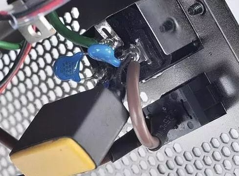
An EMI filter circuit is located at the power interface, and the better workmanship circuit also has an independent PCB board and inductor coil.
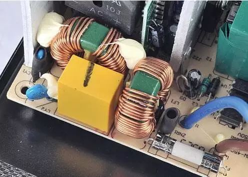
Secondary
The secondary EMI filter circuit is usually on the main PCB of the power supply and consists of inductors and capacitors.

A secondary EMI filter circuit on a poor power supply sang "Empty City Meter"
However, low-end power supplies often have only one EMI filter circuit, and slightly better power supplies should have complete one- and two-stage EMI filter circuits.
PFC circuit
PFC circuit is divided into passive and active type, and most power supplies are now active PFC.
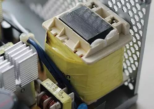
Passive PFC uses this "big" inductor
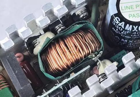
Active PFC inductors are often located in front of high-voltage filter capacitors
Passive PFC power factor is generally around 0.7, active PFC power factor is up to 0.9 or more, significantly better than passive PFC. The discrimination between the two is also quite easy.
High-voltage filter capacitor
Which are the high-voltage filter capacitors? Very simple, the highest and largest capacitance inside the power supply is (1 to 2). Comparing capacitance, in principle, can only be compared with the same type of power supply, because at the same power, the capacitive capacity required by the passive PFC power supply is greater than the active type. When comparing at the same level, we can see the capacity of the high-pressure filter capacitor, the withstand voltage value and the temperature resistance value. Theoretically, the bigger these three values ​​are, the better.
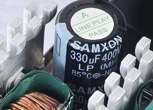
The power supply uses an active PFC, so using a high-voltage filter capacitor with a capacity of 330μF can meet the demand. The voltage value of this capacitor is 400V, and the temperature value is 85°C.
Power topology
Simply put, the topology of power supply in the previous years can be divided into half-bridge type and forward type, and now it is basically based on forward-type. The half-bridge type is a traditional power supply structure, and usually the conversion efficiency is not high; and the forward conversion efficiency of the structure is easily over 80%.
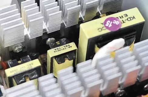
Traditional half-bridge topology
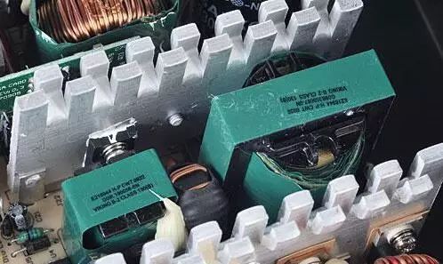
Forward topology helps improve conversion efficiency
In the resolution, we may wish to use the elimination method: in the center of the half-bridge power supply, there must be three transformers, and one big and two small, in a straight line; if your power supply is not such a structure, then congratulations, most of you It is a forward power supply.
Low-voltage filter circuit inductance coil
In the low-voltage filter circuit part, we mainly look at the inductor coil size, number of turns and color. Naturally, the larger the coil, the better the number of turns; as for the color, the theoretically superior to the inferior is gray, black, light green and yellow respectively, and the better the inductance is, the smaller the loss is.
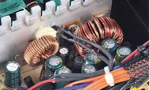
Low-voltage filter circuit mainly depends on the inductor coil
heat sink
The role of the heat sink does not need to be said. Heat exchangers and Schottky tubes are often mounted on heat sinks. At present, commercially available power supplies generally employ aluminum heat sinks, which are usually thicker and better. At the same time, in order to expand the heat dissipation area in a limited space, most of the heat sinks have fins. Theoretically, the more fins, the better.
2.54mm (.100") Pin Headers
Antenk`s line of 2.54mm pitch pin headers are durably made for high vibration environments, for board-to-board or PCB to PCB Connectors, with industry-leading current of 3.0A. Designed for low-profile applications, this pin header is made from high-temperature thermoplastic and is offered with several means of connections and mounting styles such as through-hole (THM) or surface mount (SMT) and can be in vertical (straight), elevated or at a right angle configuration/orientation
Pin header customization is also available upon your request. The 2.54mm pitch pin header is highly recommendable for signal and low power PC board connections when space is at a premium and when 1.0mm and 1.27mm pitch headers cannot dissipate the required current. In addition, the 2.54mm pitch pin header holds an excellent mating quality that fits with various types of female connectors.
Applications of 2.54mm Pitch Pin Headers
Motherboard Connectors
The Motherboard of a computer holds together many of the crucial components such as the central processing unit (CPU), memory and connectors for input and output devices.
Printer Connectors
Automotive PC Connectors
Smart, high power automotive PC power supply garners its capabilities from quality pin headers, designed for general purpose battery powered applications. These are manufactured to provide power and to control the motherboards' switch based on ignition status.
Battery Connections
Rechargeable battery packs, battery balancers, battery eliminator circuits. Battery connections rely on the ability of the current to pass reliable and solid current. This prevents overheating in the circuit and voltage drop.
Medical Diagnostic and Monitoring equipment
Communications: Telecoms and Datacoms
Industrial and Automotive Control and Test
Mount Type: Through-hole vs Surface Mount
2.54mm pitch pin (male) headers are offered in either Surface-mount or Through-hole mount termination. At one side of this pin header is a series of pins which can either be mounted and soldered directly onto the surface of the PCB (SMT) or placed into drilled holes on the PCB (THM).
Through-Hole (Poke-In)
Best used for high-reliability products that require stronger connections between layers.
Aerospace and military products are most likely to require this type of mounting as these products experience extreme accelerations, collisions, or high temperatures.
Useful in test and prototyping applications that sometimes require manual adjustments and replacements.
2.54mm vertical single row header, 2.54mm vertical dual row header, 2.54mm Elevated single row pin header, 2.54mm Elevated dual row pin Header, 2.54mm Right-angle single row header and 2.54mm Right-angle dual row header are some examples of Antenk products with through-hole mount type.
Surface-Mount
The most common electronic hardware requirements are SMT.
Essential in PCB design and manufacturing, having improved the quality and performance of PCBs overall.
Cost of processing and handling is reduced.
SMT components can be mounted on both side of the board.
Ability to fit a high number of small components on a PCB has allowed for much denser, higher performing, and smaller PCBs.
2.54mm Right-angle Dual Row pin header, 2.54mm SMT Single row pin header, 2.54mm SMT Dual row pin header and 2.54mm Elevated Dual Row Pin Header are Antenk`s SMT pin headers.
Soldering Temperature for 2.54mm Pitch Pin Headers
Soldering SMT pin connectors can be done at a maximum peak temperature of 260°C for maximum 60 seconds.
Pin-Type: Vertical (Straight) and Right-Angle
2.54mm pitch headers may be further classified into pin orientation as well, such as vertical or straight male header or right-angle male header.
One side of the series of pins is connected to PCB board in which the pins can be at a right-angle to the PCB surface (usually called "straight" or [vertical") or.
Right-Angle Pin (Male) Header Orientation
Parallel to the board's surface (referred to as "right-angle" pins).
Each of these pin-types have different applications that fit with their specific configuration.
PCB Connector Stacking
Elevated Pin Header Orientation
Elevated pins aka Stacked Pins or Mezzanine are simply stacked pin headers providing an exact distance requirement between PCBs that optimizes electrical reliability and performance between PCB boards.
This type of configuration is the most common way of connecting board-to-board by a connector. First, the stacking height is calculated from one board to another and measured from the printed circuit board face to its highest insulator point above the PCB.
Single, Dual or Multiple Number of Rows
For a 1.0mm straight or vertical male pin header, the standard number of rows that Antenk offers ranges from 1 to 2 rows. However, customization can be available if 3, 4 or n number of rows is needed by the customer. Also, the number of contacts for the single row is about 2-40 pins while for dual row, the number contacts may vary from 2-80 pins.
Pin Material
The pins of the connector have been designed with copper alloy. With customer`s demand the pins can be made gold plated.
Breakaway design
The pin headers are also equipped with a breakaway design making them fully compatible with their female receptacles.
Custom 2.54mm Pitch Pin Headers
Customizable 2.54 mm pitch pin headers are also available, making your manufacturing process way faster as the pins are already inserted in the headers, insulator height is made at the right size and the accurate pin length you require is followed.
Parts are made using semi-automated manufacturing processes that ensure both precision and delicacy in handling the headers before packaging on tape and reel.
Tape and Reel Packaging for SMT Components
Antenk's SMT headers are offered with customizable mating pin lengths, in which each series has multiple number of of circuits, summing up to a thousand individual part number combinations per connector series.
The tape and reel carrier strip ensures that the headers are packaged within accurately sized cavities for its height, width and depth, securing the headers from the environment and maintaining consistent position during transportation.
Antenk also offer a range of custom Tape and reel carrier strip packaging cavities.
Male Header,2.54Mm Male Header,2.54Mm Male Header Pins,2.54Mm Pin Header,0.100in Male Header,0.100in Pin Header Connector
ShenZhen Antenk Electronics Co,Ltd , https://www.antenkwire.com