The full name of PWM is Pulse Width ModulaTIon, which changes the equivalent output voltage by changing the duty cycle of the output square wave. Widely used in motor speed control and valve control, such as electric vehicle motor speed control is used in this way. The so-called SPWM is to change the modulation pulse mode on the basis of PWM. The pulse width time duty ratio is arranged according to the sine law, so that the output waveform can be sinusoidal output after proper filtering. It is widely used in DC AC inverters, etc. For example, advanced UPS is an example. The three-phase SPWM is a three-phase output that uses SPWM to simulate mains and is widely used in the field of inverters.
Main circuit of SPWM type inverter
The main circuit of the SPWM type inverter using single-phase power supply and three-phase power supply is shown in Figure 1 and Figure 2, respectively.
In order to limit the pumping voltage in Figure 2, the resistor R0 and the controllable transistor V0 are connected in parallel on the DC side of the circuit. When the pumping voltage exceeds a certain value, V0 is turned on, and R0 consumes excess power.
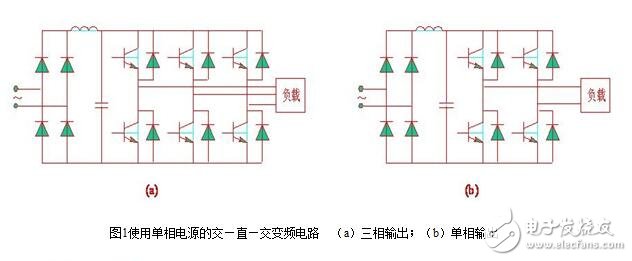
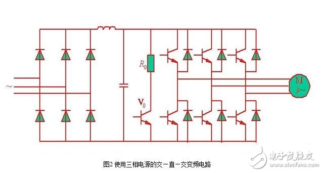
Single SPWM and three-phase SPWM control principle
Single SPWM control principle
Fig. 1 is a voltage type single-phase bridge inverter circuit using a power transistor as a switching device. ?
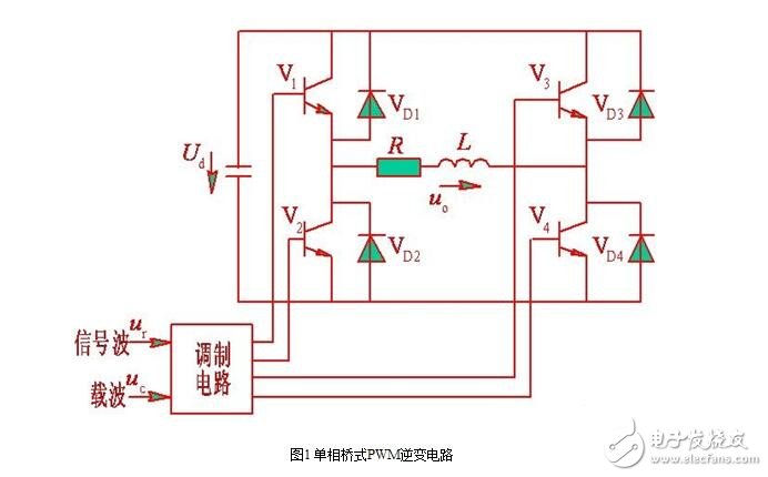
The method of controlling the on/off of V4 or V3 is shown in Fig. 2.
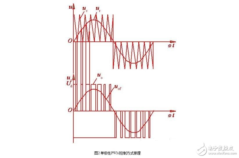
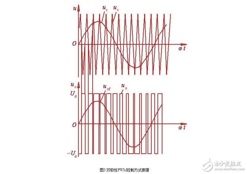
The waveform of the single-phase bridge inverter circuit shown in Fig. 1 in the bipolar control mode is shown in Fig. 3.
Three-phase SPWM control principle
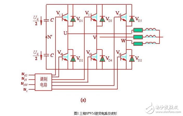
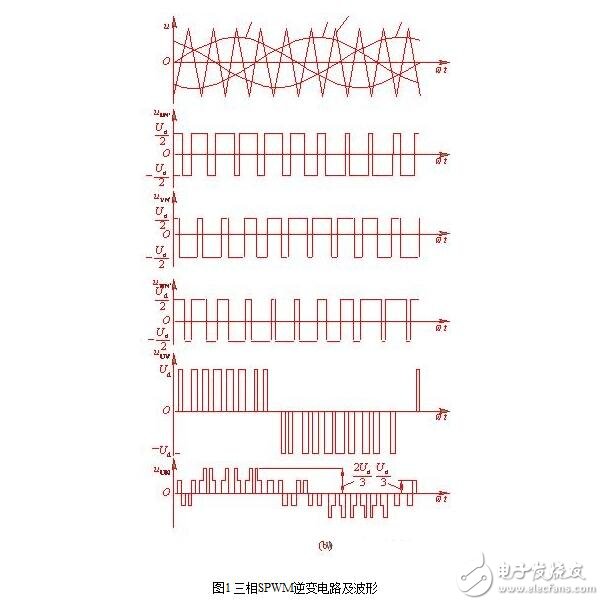
In the PWM type inverter circuit, the three-phase bridge inverter circuit shown in Fig. 1(a) is used most, and the control method is generally in the bipolar mode. The PWM control of the U, V, and W three-phases generally shares a triangular wave carrier uc, and the phases of the three-phase modulated signals urU, urV?, and urW are sequentially 120° out of phase. The control laws of the U, V, and W phase power switching devices are the same. The U phase is taken as an example. When urU "uc", the upper arm transistor V1 is turned on to give the lower arm transistor V4 a turn-off signal, and the U phase is compared with the output voltage uUN'=Ud/2 of the imaginary midpoint N' of the direct current power source. When urU "uc", V4 is turned on to give V1 a turn-off signal, then uUN' = Ud/2.
The drive signals for V1 and V4 are always complementary. When V1 (V4) is turned on, it may be that V1 (V4) is turned on, or diode VD1 (VD4) may be turned on. This is determined by the direction and magnitude of the original current in the inductive load. The same is true for the bipolar SPWM control of the phase bridge inverter circuit. The control modes of the V phase and the W phase are the same as those of the U phase. The waveforms of uUN', uVN' and uWN' are shown in Fig. 1(b). It can be seen that these waveforms are only two levels of ±Ud/2. A three-phase bridge circuit that can only output two levels like this inverter circuit phase voltage (uUN', uVN', and ?uWN') cannot achieve unipolar control.
The waveform of the line voltage uUV in the figure can be derived from uUN'-uVN'. It can be seen that when arms 1 and 6 are turned on, uUV=Ud, when arms 3 and 4 are turned on, uUV=-Ud, when arms 1 and 3 or 4 and 6 are turned on, uUV=0, thus inverse The transformer output line voltage consists of three levels: +Ud, -Ud, and zero. The load phase voltage uUN can be obtained by the following formula

As can be seen from the figure, it consists of (±2/3) Ud, (±1/3) Ud and zero total of five levels.
In the bipolar SPWM control mode, the driving signals of the upper and lower arms of the same phase are complementary. However, in order to prevent the short circuit of the upper and lower arms from being short-circuited, after applying a turn-off signal to one arm, delay the Δt time to apply an on-signal to the other arm. The length of the delay time is mainly determined by the turn-off time of the power switching device. This delay time will affect the output PWM waveform, causing it to deviate from the sine wave.
Aokit vape pod
Nanning Nuoxin Technology Co., LTD , https://www.nx-vapes.com