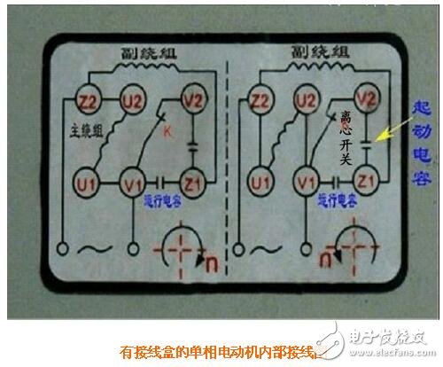
Two-phase motor is also a one-way motor. Many electricians are not very clear about the principle and circuit diagram display. Today we come to the system to learn, including three outlet single-phase motor winding judgment and single-phase capacitor motor connection. Knowledge, hope to be useful to everyone.
Two-phase motor forward and reverse connectionThere are two sets of coils in a single motor, one is the running coil (main coil), and the other is the starting coil (secondary coil). Most of the starting coils of the motor are not used only after starting, but always work in the circuit. of. The starting coil resistance is larger than the running coil resistance, and the quantity is known. The starting coil is stringed with a capacitor. That is, the starting coil of the string capacitor is connected in parallel with the running coil, and then connected to the voltage of 220V, which is the connection of the motor.
When the starting coil of the series capacitor is connected in parallel with the running coil, the head and tail of the two pairs of parallel terminals determine the forward and reverse. Single-phase motors are much more difficult than the three-phase motor's forward-reverse control. First, because single-phase motors have auxiliary devices such as starting capacitors, operating capacitors, and centrifugal switches, the structure is complicated. Second, because single-phase motors run windings and start. The windings are different and cannot be substituted for each other, which increases the difficulty of wiring. If you make a mistake, you may burn the motor.

In a single-phase motor, the main winding usually has a larger wire diameter, a smaller resistance value, and a smaller number of turns. However, some single-phase motors that are reversing are not divided into primary and secondary windings.
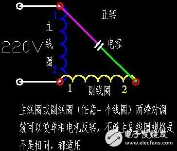
One-way motor forward and reverse principleThe 1(2) of the main coil is connected to the 2(1) of the secondary coil, so that it is transmitted positively.
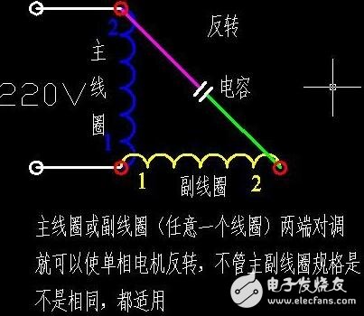
1(2) of the primary coil is connected to 1(2) of the secondary coil, and this is reversed.


In the above two figures, a general conventional single-phase motor can be used, regardless of the parameters of the main coil and the secondary coil. In addition, there is a single-phase motor that needs to be reversed during operation, but the above method is adopted. It is more troublesome, automatic control is realized, and the device needs more, so it appears that the single-phase motor that does not divide the main and auxiliary coils is the same as the parameters of the main and auxiliary coils. This can be done in addition to the above method.
Single-phase capacitor motor connectionThe single-phase motor has three taps. First, use a multimeter to block the resistance between the three wire ends. The two wires with the largest resistance are connected in parallel with the capacitor. The other wire (common terminal) is connected to one end of the power supply. Then use the multimeter's electrical blocking to measure the resistance between the common terminal and the wire ends at both ends of the capacitor. The slightly larger end of the resistor is connected to the other end of the power supply. It is absolutely forward-connected. If you want to change the direction, connect one end of the capacitor. The power cord can be connected to the other end.
Three-phase single-phase motor main winding and secondary winding are easy to judge1. First measure the resistance of the three lines, remember the two lines of the maximum value and their resistance values, and the third line is the connection point of the primary and secondary lines;
2. Measure the resistance of the contact and the two ends respectively (the sum of the two resistance values ​​must be equal to the above maximum value). The main winding is the smaller resistance value, and the secondary winding is larger. Generally, for a single-phase capacitor, the AC motor is started, and the winding connector in series with the capacitor is the secondary winding. Set the secondary winding resistance to R1 and the primary winding resistance to R2, then R1 "R2". (The main winding power is large, the resistance is small)
Use a multimeter to measure and compare the resistance between each of the three terminals. First look for the secondary winding terminal that the live wire is connected through the capacitor: the maximum resistance between it and the other two terminals (R1 in series R2), and The second largest value R1) finds the terminal with the minimum resistance value R2 and the second small resistance value R1 among the remaining two terminals, that is, the terminal of the zero line, that is, the common terminal of the main winding and the secondary winding
Why do single-phase motors have three line start capacitors and motor wiring?If the motor itself does not have a wiring diagram, only the universal meter can be used. The resistance of the three sets of resistance is measured by the resistance file. The two terminals of the largest group are the series connection of the start and the working winding, and the middle set is the working winding. Two terminals, the smaller one is the two-sided terminal of the starting winding, the working winding is connected in parallel with 220VAC, and the starting winding and the capacitor are connected in series and connected in parallel with the power supply.
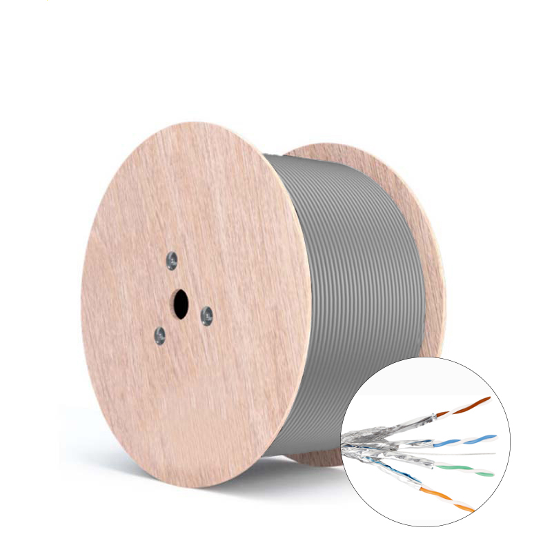
The cat7 Lan Cable are an eight-core Shield wire. Each pair has a Shield layer (commonly called a Foil Shield), and then a Shield layer (commonly called a Braided screen Shield) outside the eight cores, with the same connection as the RJ-45.The highest transmission frequency of the CAT7 Ethernet Cable S/FTP is 600MHz, and the transmission frequency of the CAT7 Network Cable is 1000MHz.
There are a number of significant differences between the six and seven cabling systems, the most obvious of which is bandwidth.The CAT6 cable of channels provide a comprehensive attenuation to crosspoint ratio of at least 200MHZ and an overall bandwidth of 250MHZ. CAT7 of systems can provide at least 500MHZ of comprehensive attenuation to crosspoking ratio and 600MHZ of overall bandwidth.
The proliferation of broadband applications has created a need for more bandwidth.For example, a typical CAT7 channel can provide a bandwidth of 862MHZ for the transmission of video signals, analog audio signals on another pair, and high-speed LAN information on a third or fourth pair.
Another difference between the CAT6 patch cable and cat7 patch cable systems is their structure.The six types of wiring systems can use either UTP or STP.The seven types of systems are based only on shielded cables.In the cat7 network cables, each pair has a shield layer, and four pairs of wires together have a common shield layer.In terms of physical structure, the additional shielding layer makes the CAT7 Ethernet Cable have a larger diameter.
Another important difference is its ability to connect hardware. The parameters of the cat7 patch cable of systems require that all pairs of wires provide at least 60DB of integrated proximal winding at 600MHZ.The cat6 systems only require 43dB at 100MHZ and 46dB at 250MHZ for the cat6 patch cable.

Cat 7 Ethernet Cord,Cat7 Lan Cable,Cat 7 Ethernet Cable,Cat 7 Network Card
Shenzhen Kingwire Electronics Co., Ltd. , https://www.kingwires.com