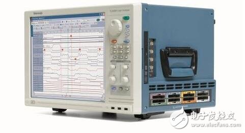
A logic analyzer is an instrument that analyzes the logical relationship of a digital system. Logic analyzer is a kind of bus analyzer in the data domain test [2] instrument, which is based on the concept of bus (multi-line), and observes and tests the data stream on multiple data lines at the same time. The instrument is very effective for testing and analyzing complex digital systems. A logic analyzer is an instrument that uses a clock to acquire and display digital signals from a test device. The primary role is timing determination. Since the logic analyzer does not have many voltage levels like an oscilloscope, usually only two voltages (logic 1 and 0) are displayed. Therefore, after the reference voltage is set, the logic analyzer determines the signal to be measured through the comparator, which is higher than the reference. The voltage is High, and the voltage below the reference voltage is Low, forming a digital waveform between High and Low.
How to use the logic analyzer:MCU development engineers and electronics enthusiasts have to deal with a variety of digital circuits every day. In addition to using tools such as multimeters and oscilloscopes, logic analyzers are also essential when making debug circuits.
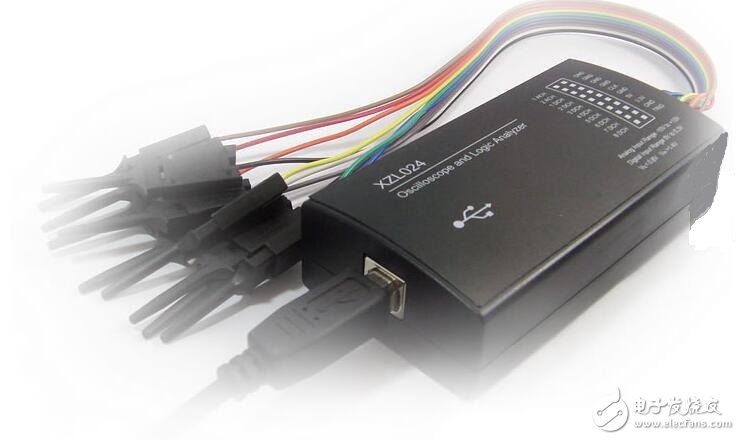
A logic analyzer is an instrument that uses a clock to acquire and display digital signals from a test device. The most important function is timing determination. Unlike an oscilloscope, a logic analyzer cannot display continuous analog waveforms, but only high and low level states (logic 1 and 0). After the reference voltage is set, the logic analyzer compares the acquired signal with the voltage comparator, which is logic 1 above the reference voltage and logic 0 below the reference voltage. In this way, the measured signals can be displayed in chronological order as continuous high and low level waveforms, which is convenient for users to analyze and debug. Using the logic analyzer, you can easily set the signal trigger condition to start sampling, analyze the timing of multiple signals, capture the interference glitch of the signal, and decode the level sequence according to the rules to complete the communication protocol analysis.
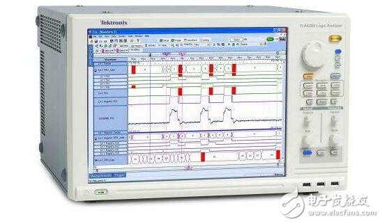
According to the function and complexity of its hardware devices, logic analyzers are mainly divided into two types: stand-alone (single-machine) logic analyzer and computer-based (PC-Base) virtual logic analyzer. The stand-alone logic analyzer integrates all software and hardware into one instrument and is easy to use. The virtual logic analyzer needs to be combined with a computer to use the powerful computing and display functions of the PC to complete data processing and display.
Professional logic analyzers, usually with a large number of sampling channels, ultra-fast sampling speed and large-capacity storage depth, but the expensive price is not personally affordable. As a development tool that engineers have at their disposal, there are many entry-level logic analyzer designs. Although the overall function cannot be compared with professional high-end instruments, it is also a very successful design to achieve specific functions at a lower cost. The logic analyzers discussed below in this article primarily refer to this type of entry-level design.
The logic analyzer based on the computer parallel port was once the mainstream, but in recent years, the computer system is no longer configured with parallel port. This type of design has become a bright future, and it only has the value of principle learning.
Another type of logic analyzer is based on low-speed microcontrollers. Many enthusiasts have designed their own works with common microcontrollers such as PIC and AVR. However, the common weakness of such single-chip logic analyzers is that the sampling speed is too slow, usually not exceeding 1 MHz.
Entry-level logic analyzers based on USB IO chips are now the most popular. For example, Saleae logic, and similar USBee. This type of product mainly uses a USB IO chip, such as CYPRESS's CY7C68013A-56PVXC. All signal triggering and processing work is done by software on the computer. The hardware part is just a data logger. The maximum sampling speed is 24MHz. They can be sampled "infinitely" because all the data is stored on the computer. Currently there are typically up to 8 channels, and more channels will proportionally reduce the maximum sampling rate. This kind of product is simple in structure, convenient and easy to use, and cheap, which is a good tool for debugging the development of single-chip microcomputer. Its main disadvantage is that the sampling speed is only 24MHz, 8 channels, it is not competent for analyzing high-speed parallel bus. For further design, it is necessary to increase the FPGA, SRAM and other devices to solve the problem of insufficient speed and insufficient number of channels.
Let's take the Saleae logic analyzer as an example to analyze the I2C bus waveform and PWM waveform by sampling, and briefly introduce its characteristics and usage methods.
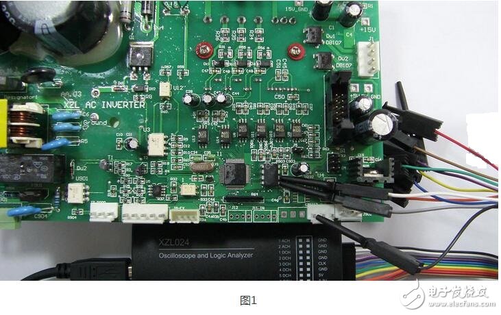
First, the process of writing data to the I2C device AT24C16 by the logic analyzer sampling MCU will be introduced. Hardware connection1. Connect the GND of the logic analyzer to the GND of the target board first, so that the two are common.
2. Select the signal to be sampled. Here is the SDA and SCL of the AT24C16. Connect the SDA to channel 1 of the logic analyzer (Input 1) and the SCL to channel 1 (Input 2).
3. Connect the logic analyzer to the computer's USB port. Windows will recognize the device and display the USB device ID in the lower right corner of the screen.
Software use1. Run the Saleae software, at which point the hardware of the logic analyzer is connected to the computer and the software will display [Connected].
2. Set the sampling quantity and speed, I2C is low speed communication, so the speed setting does not have to be too high, here set to 20M Samples @ 4M Hz speed, that is, it can continue sampling for 5 seconds.
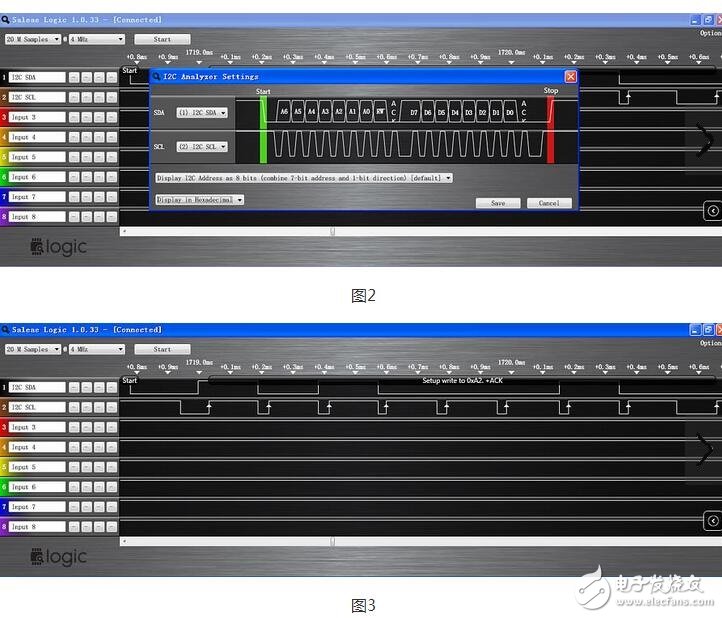
3. Set the protocol, click the "OpTIons" button in the upper right corner, find analyzer1, set to I2C protocol, as shown in Figure 1.
4. Press the "Start" button to start sampling.
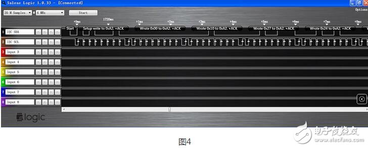
After the sampling is finished, you can see the waveform, as shown in Figure 2. Since we have set up the I2C analysis, we not only display the waveform, but also decode the displayed byte content according to the I2C protocol. The MCU writes to the AT24C16 and writes 10000 numbers at the 0x00 address. The start of the waveform is the "start" signal, which in turn is the identifier 0xA2 of the AT24C16, the write address 0x00, the data 0x10, 0x27, and so on. Since the write is in bytes, 0x2710 = 10000, indicating that the sample was successful.
Place the mouse on the waveform and click the left button to implement the zoom in function. The result is shown in Fig. 3. After the "start" condition, at the high level of the 8 consecutive pulses of SCL, the signal corresponding to SDA is 10100010, that is, 0xA2, and the ninth pulse is 0 at the high level, which is the ACK flag.
The above briefly introduces the process of I2C analysis with a logic analyzer. It can be seen that the operation is very simple.
The following describes the six PWM waveforms that use a logic analyzer to sample a three-phase AC motor driver.
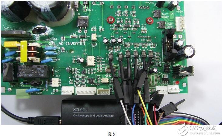
Hardware connection1. First connect the GND of the logic analyzer to the GND of the target board, so that the two are common, see Figure 5.
2. Select the signal to be sampled. Here is the output pin of the 6-channel PWM waveform of the microcontroller. Connect it to channel 1 (Input 1) of the logic analyzer to channel 6 (Input 6), and change the name of the channel to Utop. Ubottom, Vtop, Vbottom, Wtop, WBottom, respectively represent the upper and lower arms of the three outputs.
3. Connect the logic analyzer to the computer's USB port. Windows will recognize the device and display the USB device ID in the lower right corner of the screen.
Software use1. Run the Saleae software, at which point the hardware of the logic analyzer is connected to the computer and the software will display [Connected].
2. Set the number of samples and speed. The frequency of the PWM is 15 kHz, which is set to 2M Samples @ 4MHz.
3. Set the trigger condition, the default "----" will do.
4. Press the "start" button to start sampling.
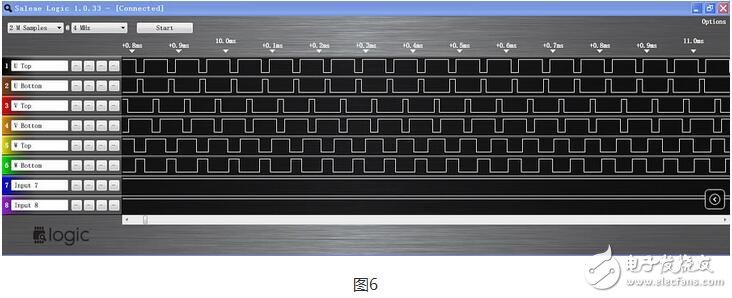
data analysisAfter the sampling is finished, you can see the waveform, as shown in Figure 6. The typical three-phase motor drive PWM is complementary, that is, the state of the upper and lower waveforms of a group of signals is opposite, respectively controlling the state of the upper and lower two switching tubes of the set of bridge arms to avoid simultaneous short circuit caused by conduction. 7.
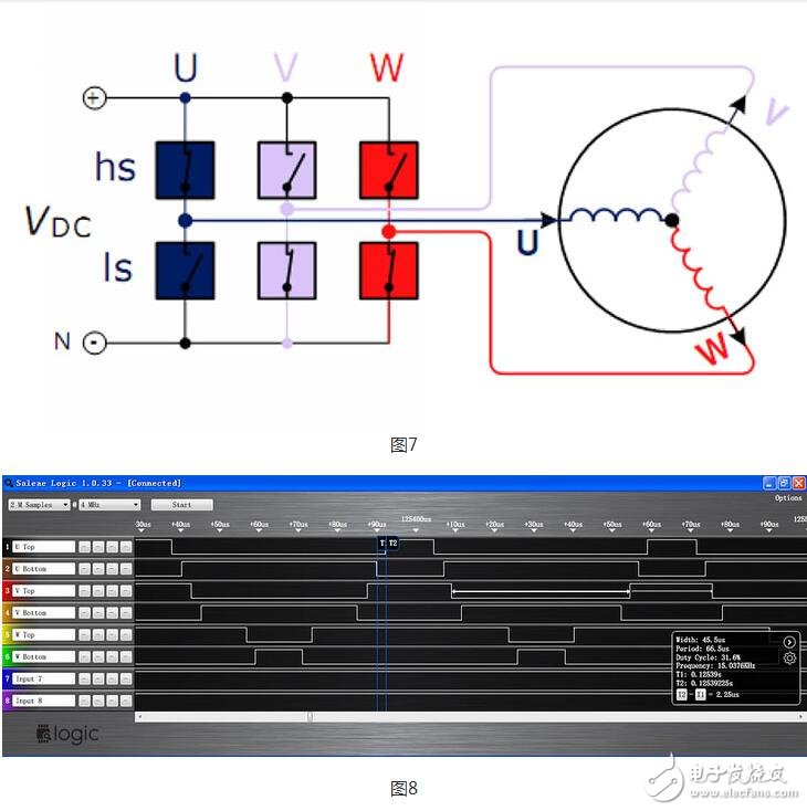
Place the mouse on the waveform and click the left button to implement the zoom in function. See Figure 8. Place the marker line on the falling edge of UBottom and the rising edge of UTop. In the lower right corner of the display box, you can see T2-T1=2.25μs, which is the time difference after turning off first, which is called “dead timeâ€. "(DeadTIme). In addition, you can see the PWM width of 45.5μs, period 66.6μs, duty cycle of 31.6%, frequency of 15.0376kHz and other information. This is the SVPWM waveform of a typical three-phase motor inverter.
The above two examples briefly introduce the use of logic analyzers, hoping to help and inspire fans.
Where are the logic analyzers mainly used:Logic analyzers are generally used for more professional digital logic analysis, generally in the following four occasions
(1) Debug and verify the operation of the digital system;
(2) Simultaneous tracking and associating multiple digital signals;
(3) Verify and analyze the operation of the time limit in the bus and the transient state;
(4) Track the execution of embedded software.
The parameters that are important in the logic analyzer are the main sampling frequency, the number of channels, the storage depth, and the types of support protocol analysis.
From the voltage level display, the logic analyzer can only observe the high and low levels (logic levels) of the signal, and the oscilloscope can observe the specific voltage level of the signal;
From the number of input channels, the logic analyzer can easily realize multi-channel (16 or more) simultaneous measurement, which is convenient for analyzing parallel signals. The oscilloscope will also achieve 4-channel simultaneous measurement.
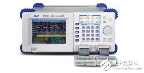
Relatively speaking, the application of logic analyzer is more inclined to the sequential logic analysis of digital circuits, and does not pay attention to the waveform structure of the signal itself; while the oscilloscope can measure the waveform of the whole signal, analyze the abnormality and interference of the signal, but it cannot be long. Time-series logic for time- and multi-channel recording signals is weak in analyzing timing logic.
Although the logic analyzer and oscilloscope are still quite different in the test principle, with the rapid development of electronic technology, the functions of the two will gradually coincide, until the two become one.
Guangzhou Yunge Tianhong Electronic Technology Co., Ltd , https://www.e-cigarettesfactory.com